
Table of Contents
Introduction
A finished conveyor roller may look mechanically simple, but producing it consistently requires much more than cutting a steel tube and installing a shaft. Tube length, end geometry, bearing-seat position, shaft features, assembly alignment, welding, and rotational behavior all depend on manufacturing accuracy established at different stages.
This is where a steel roller machine becomes important.
Rather than thinking of the equipment as a single machine performing one isolated operation, it is more useful to view steel roller production as a controlled manufacturing system. Each machine receives a workpiece in a defined condition, performs a specific operation, and prepares that component for the next stage.
For a production line, consistency between these stages often matters more than the maximum speed or capability of an individual machine.
This article explains:
- How steel roller production moves from raw tube to completed assembly
- Which processes have the greatest influence on dimensional consistency
- Why tube cutting and end preparation affect later operations
- How shaft machining influences installation and assembly
- Why fixtures and datums are critical to repeatable production
- Where automation provides practical manufacturing value
- How line balance affects real production capacity
- What should be inspected before a finished roller leaves production
- How to evaluate a steel roller machine as part of a complete manufacturing process
The objective is not simply to make a roller. It is to create a production process capable of making the same roller consistently.
What Is a Steel Roller Machine?
The term steel roller machine can refer broadly to machinery used to process or manufacture steel rollers. In conveyor roller production, it is more useful to understand the term as a group of specialized machines used for operations such as tube cutting, end machining, shaft preparation, milling, grooving, assembly, and related processing.
A machine tool controls the relationship between a workpiece and a cutting or processing mechanism. In roller manufacturing, this principle is adapted to relatively long cylindrical components whose dimensional relationships must remain consistent through several production stages.
A steel roller machine may therefore perform one dedicated operation or form part of a connected roller production line.
Typical operations include:
| Production Stage | Main Purpose | Critical Manufacturing Concern |
|---|---|---|
| Steel tube cutting | Establish roller body length | Length consistency and end condition |
| Tube-end processing | Prepare ends for assembly | Concentricity and positioning |
| Shaft cutting/machining | Produce roller shaft | Length and dimensional accuracy |
| Shaft milling | Create flats or mounting features | Feature position |
| Shaft grooving | Produce retaining features | Groove location and geometry |
| Bearing-seat assembly | Position internal components | Alignment and fit |
| Roller assembly | Combine tube, shaft and bearings | Axial and radial relationships |
| Welding | Secure required structures | Distortion and joint consistency |
| Final inspection | Verify finished roller | Dimensions, rotation and assembly |
Not every roller uses exactly the same sequence, but this framework illustrates why steel roller manufacturing should be treated as a chain of dependent operations.
Stage 1: Steel Tube Preparation Establishes the Production Baseline
The roller shell is one of the first components to enter production.
If its initial dimensions vary unnecessarily, later machines must work with inconsistent inputs. This makes tube preparation one of the most important early controls in a steel roller machine production process.
Tube diameter and wall thickness
The selected steel tube must match the intended roller design.
Diameter affects the external roller geometry, while wall thickness contributes to shell rigidity and influences how the tube behaves during clamping, machining, and assembly.
A machine setup should therefore account for:
- Tube outside diameter
- Wall thickness
- Tube straightness
- Material characteristics
- Required finished length
- Clamping behavior
A fixture suitable for one tube range may not provide the same support for another.
Straightness matters before machining begins
Machining cannot always compensate for an unstable raw component.
If a long tube already has significant geometric variation, that condition can influence locating, cutting, end processing, and final runout.
Raw-material inspection is therefore part of process control rather than something completely separate from machine performance.
Stage 2: Cutting Accuracy Influences Every Operation That Follows
Tube cutting appears straightforward, but the cut establishes an important reference for later manufacturing stages.
If finished roller bodies need consistent length, the steel roller machine used for cutting should control both material positioning and cutting behavior.
Length variation travels downstream
Suppose one tube is slightly longer than another.
The difference may later influence:
- End-processing position
- Bearing-seat location
- Overall roller length
- Assembly settings
- Welding position
- Final dimensional inspection
Operators may compensate manually, but repeated compensation increases process dependence on individual experience.
A stronger manufacturing strategy controls tube length as early as possible.
Automatic feeding can remove repeated measurement
In continuous production, repeatedly measuring every tube manually introduces another variable.
Automatic feeding and programmable length positioning can create a more predictable input for the cutting process.
The value of automation here is straightforward: it reduces the number of times an operator must manually recreate the same dimension.
Cut quality affects later locating
The end of the tube can also become a reference for another machine.
Excessive burrs, deformation, or inconsistent end condition may interfere with locating or subsequent machining.
Therefore, cutting should be evaluated according to both length and the condition of the resulting workpiece.
Stage 3: Tube-End Processing Determines Assembly Geometry
After the steel tube is prepared, its ends may require additional processing for bearing housings, end structures, or other roller components.
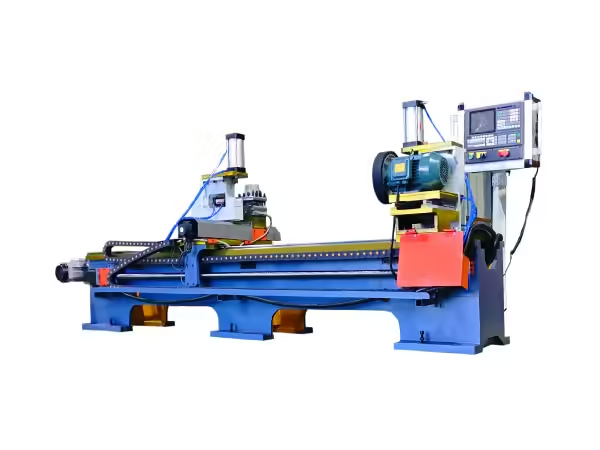
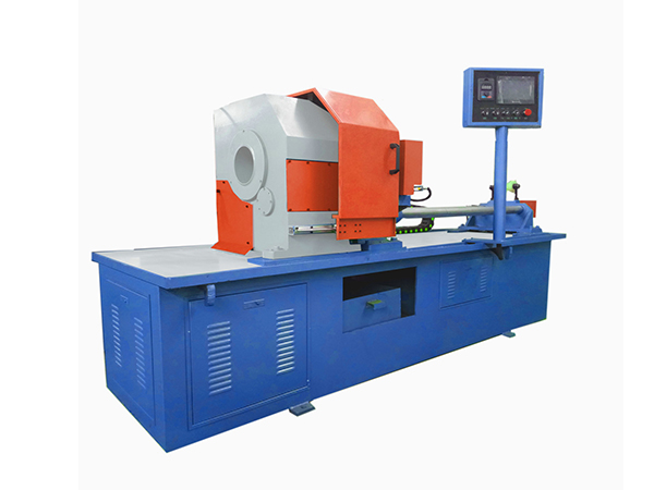
A specialized conveyor roller processing machine can perform roller-related operations around steel pipe and bearing-seat production requirements. The site’s current processing-machine range includes equipment specifically intended for steel pipe end processing.
Both ends need a controlled relationship
Processing one end accurately is not enough if the opposite end does not maintain the intended relationship.
For many roller structures, the two ends ultimately influence:
- Overall assembly length
- Bearing alignment
- Shaft relationship
- Roller rotational geometry
This makes double-end processing particularly useful where both sides need to be controlled within one manufacturing setup.
Workholding becomes critical
A long cylindrical tube requires suitable locating and support.
The fixture needs to:
- Establish a repeatable datum
- Support the tube
- Prevent unwanted movement
- Avoid excessive deformation
- Allow tool access
- Make loading practical
If the tube changes position between cycles, accurate tool movement alone cannot guarantee consistent workpieces.
Stage 4: Double-End Machining Can Reduce Datum Transfer Errors
Whenever a workpiece is removed, reversed, repositioned, and clamped again, another opportunity for positioning variation is introduced.
This is why double-end processing can be useful in steel roller production.
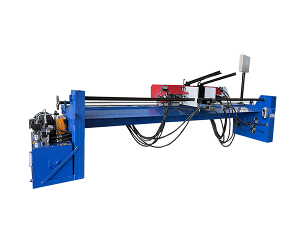
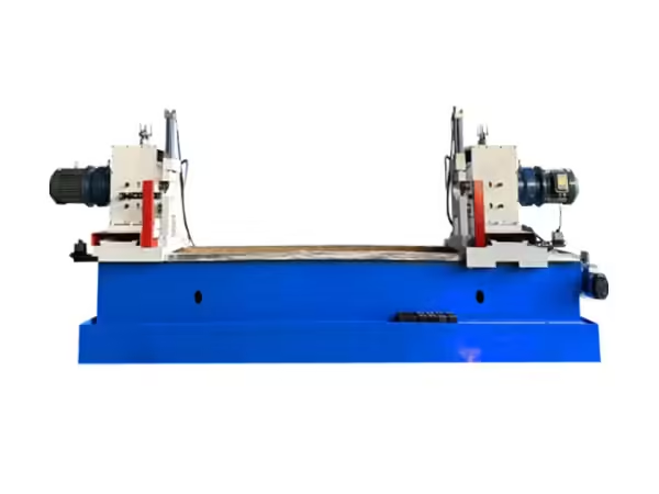
An automatic roller double end holes lathe is designed around simultaneous or coordinated roller-end processing with controlled clamping and feed, illustrating how dedicated machinery can reduce unnecessary handling between opposite ends.
Fewer setups can mean fewer positioning variables
Consider two manufacturing approaches.
Approach A:
Process first end, remove workpiece, reverse it, locate again, process second end.
Approach B:
Locate the component once and process both ends within a controlled setup.
Approach B does not automatically guarantee better results, because machine geometry and fixtures still matter. However, it removes one complete reloading and datum-transfer step.
This can simplify process control.
Symmetry matters in roller production
Conveyor rollers often require meaningful relationships between both ends.
Controlling both sides from a common setup can help engineers manage these relationships more directly.
The important point is not simply “double-end machining is faster.”
Its greater manufacturing value can come from reducing unnecessary repositioning.
Stage 5: Shaft Machining Defines How the Roller Connects to the Conveyor
The steel tube creates the roller body, but the shaft connects the finished roller to its supporting structure.
A roller shaft may contain more functional geometry than its simple appearance suggests.
Possible features include:
- Flats
- Grooves
- Threads
- Slots
- Steps
- Bearing-related surfaces
- Mounting ends
Each feature serves a particular assembly or installation requirement.
Shaft features need positional consistency
Imagine that two replacement rollers have the same overall shaft length but different flat positions.
Both shafts may appear dimensionally similar, yet only one may fit the intended bracket correctly.
This is why shaft machining needs to control not only feature size but also feature position.
Double-end shaft processing can improve consistency
As with roller tubes, processing shaft ends in a coordinated setup can reduce repeated workpiece repositioning.
The benefits can include:
- Consistent feature relationships
- Reduced manual handling
- Faster recurring setup
- More predictable component interchangeability
For large production batches, these advantages become increasingly important.
Stage 6: Fixtures Are the Hidden Accuracy System of a Steel Roller Machine
Machine specifications commonly emphasize motors, hydraulic systems, CNC controls, servo systems, and processing speed.
Fixtures deserve equal attention.
The machine knows where its tool is.
The fixture tells the machine where the workpiece is.
If those two coordinate systems do not remain consistent, final component dimensions will vary.
A good fixture performs three jobs
It locates the workpiece.
It supports the workpiece.
It holds the workpiece during processing.
Each function matters.
Locating establishes the datum.
Supporting prevents undesirable movement.
Clamping keeps the component in the intended position while forces are applied.
More clamping force is not always better
Steel tubes can still deform when clamped incorrectly, especially where wall thickness, tube length, and contact geometry create local sensitivity.
The fixture should apply force in a way that stabilizes rather than changes the component.
Fixture wear should be anticipated
Repeated loading causes contact surfaces to experience wear.
Over time, worn locating surfaces can introduce gradual dimensional drift.
A production-ready steel roller machine should therefore make critical locating points:
- Inspectable
- Maintainable
- Replaceable where appropriate
- Easy to verify
Fixture maintenance belongs inside the quality system.
Stage 7: Bearing and Housing Assembly Controls Roller Rotation
The bearing system connects the rotating shell with the stationary or supported shaft arrangement.
Even accurately machined components can produce an unsatisfactory finished roller if assembly alignment is poor.
Pressing needs positional control
Bearing housings and related components need to enter the roller body at the intended position and orientation.
Important factors may include:
- Pressing direction
- Positioning depth
- Component alignment
- Applied force
- Tube support
- Simultaneous end relationships
An assembly operation should control both component position and how force travels through the workpiece.
Excessive force can hide upstream problems
If an assembly suddenly requires much greater force than normal, simply increasing press force may not be the correct response.
Possible upstream causes could include:
- Dimensional variation
- Misalignment
- Component deformation
- Incorrect preparation
- Contamination
- Fixture changes
A stable production system treats abnormal assembly force as process information.
Stage 8: Welding Must Control Both Joint Quality and Distortion
Where the roller structure requires welding, the operation introduces another important manufacturing variable: heat.
Welding creates a local thermal cycle.
If the workpiece is not positioned and supported correctly, that thermal input can affect finished geometry.
Fixture stability matters during welding
The welding fixture should maintain the required component relationship throughout the operation.
Useful considerations include:
- Axial location
- Concentric positioning
- Joint consistency
- Rotation
- Welding sequence
- Workpiece support
The goal is not simply to create a complete weld.
The goal is to create the joint without unnecessarily disturbing the roller geometry established by previous operations.
Process consistency matters more than visual consistency alone
A visually uniform weld can be useful, but production assessment should also consider whether the welding process consistently maintains the required assembly dimensions.
When welding is part of the steel roller machine line, the process should be evaluated as both a joining operation and a geometric-control operation.
Stage 9: Automation Should Remove Repetitive Sources of Variation
Automation provides the greatest benefit when it replaces repetitive manual decisions that influence product consistency.
For steel roller production, effective automation can include:
- Automatic feeding
- Automatic length positioning
- Hydraulic or automatic clamping
- Programmable machining positions
- Servo-controlled movement
- Stored product parameters
- Automatic processing cycles
- Workpiece detection
- Controlled unloading
The number of automated functions is less important than what they control.
Automate the repeated decision
If an operator repeatedly measures the same distance, programmable positioning may help.
If different operators use different clamping sequences, automatic clamping may improve consistency.
If product changes require several settings, stored parameters may reduce setup mistakes.
Automation should have a clear reason.
Do not automate an unstable mechanical process
If the fixture cannot locate the tube consistently, adding sensors does not fix the underlying geometry.
If tooling is unsuitable, faster automatic cycling simply repeats an unsuitable cutting condition.
A strong steel roller machine should therefore establish stable mechanical fundamentals before additional automation is introduced.
Stage 10: Production Line Balance Matters More Than the Fastest Machine
One machine can be highly productive while the complete roller line remains inefficient.
This usually happens when capacity differs significantly between connected operations.
Consider an illustrative process:
| Operation | Example Cycle | Potential Constraint |
| Tube cutting | 20 sec | Material feeding |
| End processing | 28 sec | Machining |
| Shaft processing | 26 sec | Loading and positioning |
| Bearing assembly | 24 sec | Component supply |
| Welding | 32 sec | Welding cycle |
| Inspection | 25 sec | Measurement |
These figures are examples for production analysis, not performance specifications.
In this example, reducing tube cutting from 20 to 15 seconds would not automatically increase finished roller output because the 32-second welding process remains slower.
Find the actual bottleneck
The constraint may not even be the machine with the longest programmed cycle.
Real bottlenecks can result from:
- Loading
- Changeover
- Tool replacement
- Manual measurement
- Material supply
- Inspection
- Machine adjustment
- Workpiece transfer
For this reason, steel roller machine capacity should be evaluated through the entire operating cycle.
Buffering should be intentional
Some production lines use intermediate buffers between machines.
Buffers can prevent a short interruption at one station from immediately stopping every connected process.
However, excessive work-in-progress can also hide unstable line balance.
The goal is controlled flow, not simply accumulating components between machines.
How to Evaluate Finished Steel Roller Quality
A finished roller should be evaluated according to its functional requirements.
External appearance alone provides limited information about how it will perform once installed.
A practical inspection plan may include:
Overall dimensions
Check dimensions that affect conveyor installation and component interchangeability.
These can include:
- Roller length
- Shell diameter
- Shaft length
- Shaft-end dimensions
Rotational geometry
Runout can provide useful information about the relationship between the roller shell and its rotational axis.
Potential sources of variation include:
- Tube geometry
- Bearing housing position
- Shaft alignment
- Welding distortion
- Assembly differences
Rotation behavior
The roller should rotate in a manner appropriate for its intended assembly.
Unusual resistance can provide clues about:
- Bearing condition
- Seal installation
- Internal alignment
- Assembly force
- Contamination
Shaft feature position
Grooves, flats, threads, and mounting features should be checked where they affect installation.
Weld and assembly condition
Where applicable, welded and assembled areas should be examined according to the technical requirements established for the roller design.
Steel Roller Machine vs General-Purpose Equipment
General-purpose machines can process a wide variety of components. Specialized roller machinery is designed around a narrower family of recurring operations.
Neither approach is universally correct.
| Factor | General-Purpose Equipment | Specialized Steel Roller Machine |
| Product range | Broad | Focused on roller-related parts |
| Setup flexibility | High | Designed around defined roller ranges |
| Fixture design | Often application-created | Can be integrated into machine design |
| Operator input | Usually greater | Can be reduced through dedicated controls |
| Repeated production | Depends heavily on setup | Designed for recurring operations |
| Double-end processing | Depends on machine configuration | Can be designed into the process |
| Automation | General-purpose | Can target roller-specific tasks |
| Line integration | Requires additional planning | Can be planned around roller production |
The important distinction is process frequency.
If the same family of roller components is produced repeatedly, specialized equipment can embed recurring production requirements directly into the machine design.
What Information Should Be Prepared Before Selecting a Steel Roller Machine?
Equipment selection becomes much more effective when the workpiece and process are defined first.
Prepare information in several categories.
Roller specifications
Include:
- Roller diameter range
- Roller length range
- Steel tube specifications
- Shaft dimensions
- Bearing arrangement
- Bearing housing type
- Shaft-end structure
Processing requirements
Define which operations are required:
- Tube cutting
- End machining
- Shaft milling
- Shaft grooving
- Bearing assembly
- Welding
- Other relevant processes
Product variation
Explain which roller specifications are produced frequently and which occur only occasionally.
This helps determine the appropriate level of flexibility.
Production expectations
Instead of supplying only a desired output figure, explain:
- Operating hours
- Product mix
- Changeover frequency
- Manual loading expectations
- Adjacent equipment
This provides a better basis for line balancing.
Drawings
Technical drawings remain one of the clearest ways to communicate:
- Dimensions
- Tolerances
- Shaft features
- Assembly relationships
- Critical positions
A drawing can reveal requirements that may be overlooked in a written equipment request.
Common Steel Roller Machine Selection Mistakes
Several errors can reduce the performance of an otherwise capable production line.
Selecting equipment before defining roller specifications
A machine should follow the product requirement.
The product should not be redesigned unnecessarily just to fit an equipment assumption.
Comparing only processing speed
Cycle time has limited meaning without loading, unloading, changeover, and adjacent-process capacity.
Ignoring fixtures
Highly capable controls cannot fully compensate for unstable workpiece positioning.
Using maximum machine range as the main selection standard
A wide range can be useful, but normal production should operate comfortably within the machine’s practical capability.
Ignoring tooling replacement
A machine should remain practical when tools wear and require routine replacement.
Ignoring downstream requirements
The finished component from one machine needs to be suitable for the next process.
Evaluating only one processed sample
A single sample demonstrates possibility.
Several consecutive samples provide better evidence of repeatability.
A Practical Evaluation Framework
Before finalizing steel roller equipment, evaluate the machine against the actual manufacturing process.
| Evaluation Area | Main Question |
| Workpiece fit | Does the machine match normal roller dimensions? |
| Process fit | Does it perform the required operation correctly? |
| Datum control | How is the component located? |
| Clamping | Is workholding stable without unnecessary deformation? |
| Repeatability | Can results be maintained across repeated cycles? |
| Tooling | Are tools suitable and practical to replace? |
| Automation | Which production variation does it remove? |
| Changeover | How easily can normal roller specifications be changed? |
| Capacity | Does the machine match adjacent processes? |
| Maintenance | Are common service areas accessible? |
| Inspection | How is finished output verified? |
This framework shifts the discussion away from isolated specifications.
It asks whether the machine can function as a predictable production asset.
Conclusion
A steel roller machine should be evaluated according to the complete roller manufacturing process rather than one machining operation.
Production begins with the steel tube.
Tube preparation establishes the initial geometry. Cutting controls length. End processing prepares the shell for subsequent assembly. Shaft machining creates installation features. Bearing-related operations establish the rotational structure. Welding joins components while introducing thermal considerations. Final inspection verifies whether these stages have produced a consistent roller.
Throughout this process, fixtures establish datums, tooling creates features, automation controls repeated actions, and machine design determines how reliably the process can be reproduced.
The strongest production line is not necessarily the one containing the fastest individual equipment.
It is the line in which every steel roller machine receives a predictable input, performs a controlled operation, and provides the next stage with a consistent component.
For manufacturers planning automated roller production, this is the more useful measure of equipment quality: not simply whether the machine can make a roller, but whether it can repeatedly support a stable manufacturing process from steel pipe to finished roller.
FAQ
What is a steel roller machine used for?
A steel roller machine is used for one or more processes involved in manufacturing steel rollers, such as tube cutting, end machining, shaft processing, milling, grooving, bearing-related assembly, or welding. Specialized equipment is usually designed around recurring roller dimensions and production requirements.
What equipment is needed for steel conveyor roller production?
The required equipment depends on roller design. A typical line may include steel tube cutting, tube-end processing, shaft machining, flat milling or grooving, bearing housing assembly, roller assembly, welding, and inspection equipment. The correct sequence should follow the actual component structure.
Why is double-end processing useful in a steel roller machine?
Double-end processing can reduce repeated workpiece repositioning by controlling both ends within one coordinated setup. This can simplify datum relationships, reduce handling, and improve consistency between opposite features. Actual performance still depends on machine geometry, fixtures, tooling, and setup control.
How does automation improve steel roller machine production?
Automation can reduce repeated manual measuring, positioning, clamping, parameter setting, and material handling. Its greatest value comes from controlling known sources of production variation. Automatic functions should support a stable mechanical process rather than compensate for poor fixtures or unsuitable tooling.
How should the quality of a steel roller machine be evaluated?
Evaluate workpiece range, fixture design, datum control, machine rigidity, tooling, repeatability, automation, changeover, complete production cycle, maintenance access, and output inspection. Repeated processing of representative components provides stronger evidence of capability than one carefully prepared sample.
 English
  French
  Spanish