

Table of Contents
Introduction
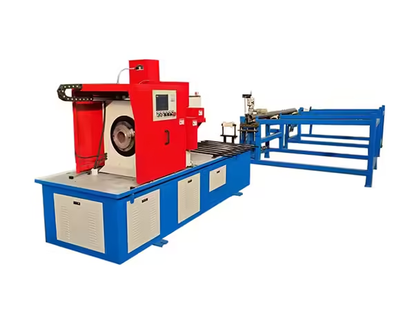
A round pipe cutting machine performs one of the earliest dimensional operations in conveyor roller manufacturing. Before a steel tube can become a roller shell, raw round pipe needs to be divided into blanks with controlled length, stable end geometry, and a cutting condition suitable for the machining stages that follow.
This operation may appear straightforward, but variation created during cutting can continue through the entire roller manufacturing process. Inconsistent blank length affects double-end tube machining, while unstable clamping or worn tooling can change the end face and increase the amount of correction required during later processing.
For repetitive roller production, the cutting machine therefore needs to control material feeding, workpiece centering, clamping, cutter movement, spindle speed, and production sequencing as one coordinated system. This guide explains how these functions work together in a round steel pipe cutting application and why the machine should be evaluated according to the complete roller production process rather than cutting speed alone.
What Is a Round Pipe Cutting Machine?
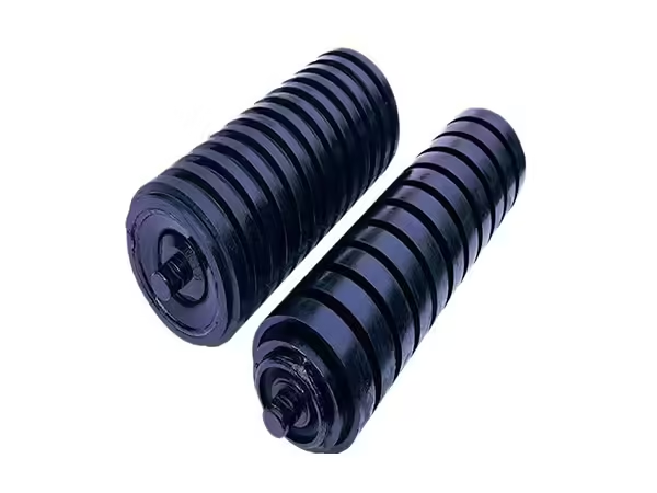
A round pipe cutting machine is specialized equipment designed to divide cylindrical steel pipe into controlled sections. In conveyor roller manufacturing, these sections later become the outer shells of the finished rollers.
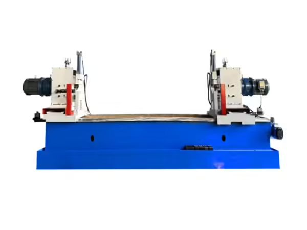
The existing Pipe Cutting Machine automatically completes material feeding, positioning, hydraulic clamping, and mechanical cutting. The workpiece remains stationary during the cutting operation, while the cutter holder rotates around the pipe.
This structure is particularly suitable for long round stock because the complete steel pipe does not need to rotate at cutting speed. The material only moves longitudinally during feeding and remains fixed once it reaches the programmed cutting position.
For roller manufacturing, this creates a predictable relationship between feeding distance and finished tube length while maintaining stable support for long raw material.
Why Round Steel Pipe Needs a Dedicated Cutting Process
A conveyor roller shell is fundamentally a straight cylindrical component. The pipe normally needs a clean transverse cut rather than a complex profile, branch opening, or irregular contour.
This makes dimensional repeatability especially important. The manufacturing objective is to produce one controlled blank after another so that downstream machinery receives workpieces with similar starting dimensions.
A round pipe cutting machine can therefore concentrate on several specific requirements: consistent blank length, suitable end-face condition, stable centering, controlled burr formation, and repeatable batch production.
The cutting stage does not create the final precision geometry of the roller tube. Instead, it creates a predictable starting workpiece for the machining operations that follow.
QZ160 Working Range
The QZ160 configuration is designed specifically for medium-thickness round steel pipe commonly used in conveyor roller production.
| Technical Item | QZ160 Reference |
|---|---|
| Pipe diameter | Φ60–159 mm |
| Wall thickness | 3–8 mm |
| Main motor | 5.5 kW |
| Workpiece movement | Stationary during cutting |
| Cutting-tool movement | Rotating |
| Clamping | Hydraulic self-centering |
| Feeding | Servo motor + ball screw |
| Single feeding length | 20–1200 mm |
| Tool options | White steel / carbide |
| Feed rate | 0.09/r |
| Example cutting cycle | Approx. 15 s at Φ89 × 2.5 mm |
These parameters should be read as one operating range rather than as independent maximum values. Pipe diameter, wall thickness, finished blank length, tooling, and raw material support all influence the actual production setup.
Servo Feeding Controls Blank Length
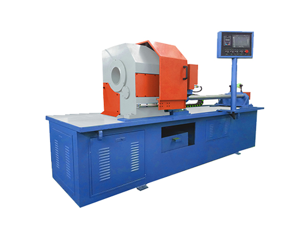
A cutting tool cannot produce repeatable roller shells if the steel pipe stops at a different location during every cycle. Material feeding is therefore one of the most important functions in an automatic round pipe cutting machine.
The QZ160 uses a servo motor together with a ball screw to move the raw pipe longitudinally. The control system determines the required travel, after which the mechanical transmission moves the pipe toward the cutting position.
This arrangement reduces dependence on repeated manual measurement and allows the same feed distance to be reproduced across a production batch.
The physical result still needs to be verified. Mechanical wear, material support, ball-screw condition, or movement during clamping can influence the finished length even when the programmed feed value remains unchanged.
Why Ball-Screw Feeding Matters
A ball screw converts rotational movement from the drive system into controlled linear motion. In a pipe-feeding application, this allows programmed movement to be translated into actual longitudinal pipe travel.
Its usefulness comes from repeatability rather than from automation alone. The machine can return to similar feed movements during repeated production, creating a stronger dimensional basis for batch cutting.
Ball-screw condition should therefore be included in routine maintenance. Wear, contamination, inadequate lubrication, or mechanical looseness can gradually change positioning behavior.
If tube length begins drifting during a production batch, the complete feeding mechanism should be inspected before software values are changed simply to compensate for the physical variation.
Hydraulic Self-Centering Clamping
Once the pipe reaches the required position, it needs to remain stable until the cutter has completed the separation process.
The QZ160 uses hydraulic self-centering clamping. This is particularly useful for round steel pipe because it helps maintain the workpiece around the intended machine centerline while simultaneously preventing longitudinal movement.
Clamping performs two functions at the same time. It protects the feeding position established by the servo system and creates a stable relationship between the pipe and rotating cutter.
If the workpiece shifts after positioning, the feeding system may have performed correctly while the final blank still becomes dimensionally inconsistent.
Why Self-Centering Is Important for Round Pipe
Cylindrical workpieces can move easily if the clamping structure does not establish a stable center reference.
A self-centering system reduces the amount of manual adjustment required when similar round pipes are processed repeatedly. Both sides of the clamp act around the pipe so the workpiece remains closer to the intended cutting axis.
The clamping surfaces still need to remain clean and correctly adjusted. Metal chips, contamination, hydraulic problems, or uneven wear can gradually change how the pipe sits inside the machine.
First-piece verification after a diameter change provides a practical way to confirm that the new clamping condition remains suitable.
The Pipe Remains Stationary During Cutting
One of the defining characteristics of the machine is its stationary-workpiece design. During the actual cutting process, the steel pipe does not rotate. Instead, the cutter holder moves around the pipe.
This arrangement becomes increasingly useful as raw stock length increases. Rotating a long steel pipe would require the complete material length to remain balanced and supported while moving at cutting speed.
Keeping the workpiece stationary avoids this requirement. The pipe can remain supported along the feed line while the cutting action is concentrated at one specific point.
For roller shell production, where repeated straight transverse cuts are required, this creates a practical mechanical structure without introducing unnecessary movement of the complete raw stock.
How Mechanical Pipe Cutting Works
Pipe cutting can be performed using several technologies depending on material and required geometry. In this roller-production application, the process uses a mechanical cutting tool rather than a laser, plasma arc, or flame.
The raw pipe advances to position and is clamped securely. The cutter holder then rotates around the stationary workpiece while the tool feeds progressively through the pipe wall.
Once the section is fully separated, the cutting unit retracts, the clamp releases, and the feeding mechanism advances the next required length.
This cycle can then repeat for each roller shell blank within the production batch.
Pipe Diameter and Wall Thickness Need to Be Evaluated Together
Outside diameter alone does not describe the cutting condition.
A Φ108 mm pipe with a relatively thin wall presents a different cutting load from another Φ108 mm pipe with a substantially thicker wall. Tool engagement, cutting resistance, cycle condition, and cutter wear can all change.
The QZ160 is designed around approximately Φ60–159 mm outside diameter and 3–8 mm wall thickness. Both limits should therefore be checked against the actual raw material.
Selecting equipment only because the pipe diameter fits the nominal range can overlook an equally important wall-thickness requirement.
Raw Pipe Straightness Affects Feeding
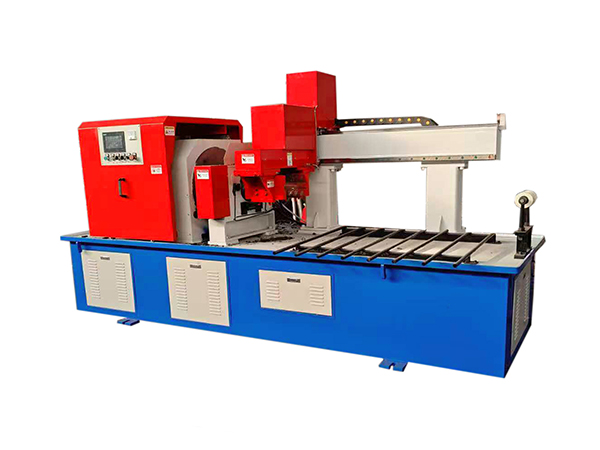
The cutting process begins before the pipe enters the cutter.
Long raw material should remain reasonably straight and supported so it can move through the feeding system without unnecessary side loading or binding. Significant curvature can influence how the pipe passes through the machine and how consistently it reaches the clamping position.
Material support racks should therefore maintain the pipe close to the machine feeding axis.
This becomes particularly important with longer raw stock because a small alignment difference at the far end can create a larger positional effect near the cutting machine.
Support of Long Raw Material
A production facility may process steel pipe supplied in lengths considerably longer than the finished roller shells.
Supporting this raw material is part of the cutting system even though the rack itself may sit outside the machine body. The pipe needs a controlled path toward the spindle so the servo system does not also need to overcome unnecessary sagging or lateral movement.
Roller supports or suitable feeding racks should allow longitudinal movement while maintaining reasonable alignment.
A highly accurate servo feed provides limited benefit if the raw material approaches the machine at an unstable angle.
Tool Selection Influences the Cutting Process
The QZ160 can use white steel or carbide cutting tools according to the processing requirement.
Tool material and geometry influence cutting resistance, surface condition, burr formation, and tool life. The most suitable option depends on steel pipe characteristics and the established machining process.
A tool should not remain in service simply because it can still separate the material. Gradual edge deterioration can change the quality of the finished blank before complete tool failure occurs.
Regular inspection of the cut surface can therefore provide useful feedback about cutter condition.
Tool Wear and Burr Formation
Burr formation is one of the clearest indicators of changing cutting conditions.
A fresh and properly configured cutter can produce a relatively controlled end edge. As the tool wears, cutting resistance can increase and the remaining material at the end of the cycle may become less consistent.
Heavy burrs can interfere with handling and may require additional correction before the next machining operation.
When burr formation gradually increases during a batch, tooling should be inspected before machine settings are changed unnecessarily.
Spindle Speed Needs to Match the Workpiece
The spindle uses variable-frequency stepless speed regulation, allowing cutting conditions to be adapted for different pipe specifications.
The correct spindle speed depends on the relationship between pipe diameter, wall thickness, material, tool type, and cutting feed.
Higher speed is not automatically better. Excessive speed can create unsuitable cutting conditions, while very low speed can reduce process efficiency or alter tool engagement.
Validated settings for frequently manufactured pipe sizes can help make changeovers more repeatable.
Why Machine Rigidity Matters
During cutting, the tool applies force to the steel pipe. The spindle, tool holder, clamp, frame, and feeding structure need to maintain their relative positions while this load is applied.
If machine components move excessively, the resulting end face and cutting behavior can become less stable.
Machine rigidity therefore supports the accuracy created by the servo feeding and clamping systems.
Changes in vibration, sound, or cutter behavior should be treated as useful maintenance signals rather than ignored until the machine can no longer complete a cut.
End-Face Condition Affects Downstream Machining
The pipe blank produced by the cutting machine is an intermediate workpiece, not the finished roller tube.
After cutting, the tube may enter double-end machining so its end geometry can be prepared for bearing housings or other roller components.
The existing Automatic Roller Double End Holes Lathe is designed specifically for processing both ends of steel pipe used in belt conveyor rollers.
This creates a direct relationship between cutting quality and the following machining stage. A consistent pipe blank gives the double-end lathe a more predictable starting workpiece.
Why Blank Length Matters Downstream
Downstream machinery normally expects the workpiece to arrive within a defined dimensional range.
If blank length varies significantly, cutting tools or fixtures at the next stage may need to compensate for inconsistent starting geometry. This makes process control more difficult even when the downstream machine itself is accurate.
Stable blank length therefore reduces unnecessary variation between manufacturing stages.
This is one reason the round pipe cutting machine should be viewed as the first dimensional control point in roller shell production rather than simply a material-separation device.
Parallelism of the Cut End
A cut that is noticeably angled relative to the pipe axis creates different starting conditions around the circumference of the tube.
Later end machining may correct this geometry, but excessive angular variation increases the amount of material that the next machine must remove.
The cutting system should therefore aim for a stable transverse end condition consistent with the requirements of the following process.
Tool condition, workpiece centering, spindle alignment, clamping, and mechanical rigidity all influence the resulting cut.
PLC Sequencing and Automatic Operation
An automatic pipe cutting cycle requires several actions to occur in the correct order.
The material feeds to position, clamping secures the workpiece, the cutting tool advances, the pipe is separated, the cutter retracts, the clamp releases, and the next feeding cycle begins.
PLC-based control coordinates these operations so they follow a repeatable sequence.
Automation reduces repeated manual actions but does not remove the need for correct mechanical setup. The PLC can reproduce the same command accurately even if a worn tool or misaligned clamp is producing an unsuitable physical result.
First-Piece Inspection After a Setup Change
Whenever pipe diameter, wall thickness, cutting length, tooling, or another major parameter changes, the first completed blank should receive additional inspection.
The operator should verify finished length, end-face condition, burr formation, visible deformation, and any other dimension required by the following production stage.
This confirms whether the new setup produces the expected physical workpiece before the machine repeats the same cycle across a larger batch.
Automatic equipment makes first-piece inspection more important, not less important, because an incorrect setup can otherwise be reproduced very efficiently.
Monitoring Length During Batch Production
A correct first workpiece does not guarantee that the process will remain unchanged throughout a long batch.
Tool wear, feeding-system condition, raw material variation, or clamp contamination can gradually influence the result.
Periodic measurement allows technicians to recognize this drift before it affects a large group of tube blanks.
Inspection frequency should reflect the production environment, workpiece specification, and stability of the established process rather than relying on one universal interval.
Diagnosing Cutting-Length Variation
When finished blank length begins changing, troubleshooting should follow the workpiece movement through the machine.
Raw pipe support should be checked first, followed by servo feeding, ball screw condition, guides, positioning, and hydraulic clamping.
If the pipe feeds accurately but moves during clamping or cutting, adjusting the programmed feed distance will not correct the actual problem.
A structured diagnosis prevents software adjustments from being used to hide mechanical variation.
Diagnosing Angled Cut Faces
An angled or inconsistent cut face can result from several mechanical conditions.
Tool condition, spindle alignment, pipe centering, clamp stability, and workpiece support should all be checked. If the pipe is not centered correctly relative to the rotating cutter, the tool may engage the circumference unevenly.
Technicians should compare several consecutive workpieces to determine whether the condition is consistent or random.
A repeatable pattern often provides stronger information about the source of the problem than one isolated tube.
Diagnosing Excessive Vibration
Unexpected vibration during cutting can indicate cutter wear, poor tool mounting, spindle problems, unsuitable workpiece support, or clamping instability.
The machine should not simply continue operating until the vibration begins affecting visible dimensions.
Changes in sound and vibration can provide early warnings that the cutting system is moving away from its normal condition.
Investigating these signs early protects both cutter condition and blank consistency.
Maintenance of the Feeding System
Servo motors, ball screws, and associated feeding components need to remain clean, aligned, and properly maintained.
Lubrication should follow the machine requirements, while accumulated chips and contamination should be prevented from entering sensitive movement areas.
Fasteners and couplings should also remain secure because mechanical looseness can gradually introduce positioning variation.
When feeding accuracy changes, maintenance history can help determine whether the cause developed gradually or appeared immediately after another machine adjustment.
Maintenance of Hydraulic Clamping
Hydraulic clamping depends on stable pressure and correctly functioning mechanical components.
Leaks, worn seals, contaminated contact surfaces, or irregular actuator movement can change the way the pipe is held.
Clamping surfaces should remain clean so each round pipe contacts the fixture consistently. Hydraulic components should also be inspected for changes in movement or holding condition.
Because clamping preserves the feeding position during cutting, maintenance in this area directly supports final blank accuracy.
Maintenance of the Cutter and Spindle
The cutter and spindle perform the actual separation process, making their condition central to end-face quality.
Tool mounting should remain secure, while the spindle should rotate without abnormal vibration or looseness.
Tool wear should be monitored using both operating time and finished-workpiece condition. A cutter may still complete the operation while already producing heavier burrs or poorer surface consistency.
Replacing or servicing the tool before severe deterioration develops helps protect downstream production.
Why Roller Production Benefits From Dedicated Cutting Equipment
A general workshop saw can separate steel pipe, but repetitive conveyor roller production requires controlled feeding, clamping, and cut positioning across many similar workpieces.
A dedicated round pipe cutting machine organizes these functions around long cylindrical material. The pipe moves through one defined feed path, is centered automatically, remains stationary during cutting, and advances again for the next blank.
This structure reduces repeated manual measurement and creates a more stable connection between raw steel pipe and downstream roller processing.
The value comes from process repeatability rather than from performing a large number of unrelated cutting operations.
Common Mistake: Selecting Only by Maximum Diameter
Maximum pipe diameter is one of the easiest machine specifications to compare, but it does not describe the complete cutting requirement.
Wall thickness, finished length, raw stock support, cutting tool, production volume, and downstream machining all matter.
A pipe can fall within the nominal diameter range while still requiring a wall thickness or cutting condition outside the intended process.
Machine selection should therefore use the complete raw-material specification rather than one headline dimension.
Common Mistake: Ignoring Raw Material Support
An automatic feeding system cannot perform at its best when the raw pipe is poorly supported.
Long stock that sags or approaches the machine at an angle can increase mechanical resistance and change how the pipe reaches the clamping position.
Support racks should therefore be considered part of the production system.
Improving the machine while ignoring the material path leading into it can leave an important source of variation unresolved.
Common Mistake: Waiting for Complete Tool Failure
A cutting tool normally changes gradually rather than failing without warning.
Increasing burr formation, rougher end surfaces, longer cycle behavior, changing sound, or greater vibration can all indicate wear before the tool becomes unusable.
Continuing production through this deterioration allows inconsistent blanks to enter downstream machining.
Tool inspection should therefore be preventive rather than reactive.
How Round Pipe Cutting Fits the Roller Workflow
A controlled roller manufacturing process begins with raw material and gradually adds the geometry required by the final component.
Round steel pipe is cut into blanks first. The tube ends can then be machined, followed by bearing-related assembly, shaft installation, sealing, welding, and final inspection according to the roller design.
The cutting machine establishes the initial shell length used by all later operations.
This makes cutting an upstream quality-control stage whose influence continues long after the tube has left the machine.
Conclusion
A round pipe cutting machine for conveyor roller production needs to do more than separate steel pipe. It establishes the first controlled dimensions of the roller shell and therefore influences the machining stages that follow.
The QZ160 uses servo motor and ball-screw feeding, hydraulic self-centering clamping, variable-frequency spindle control, and a stationary-workpiece rotating-tool structure. Its working range of approximately Φ60–159 mm and 3–8 mm wall thickness is designed around repeated round steel pipe processing.
Reliable production still depends on raw material support, tool condition, feeding-system maintenance, clamping stability, spindle behavior, first-piece verification, and periodic inspection. When these factors are controlled together, the machine can deliver more predictable tube blanks to double-end machining and the later stages of conveyor roller production.
FAQ
What is a round pipe cutting machine used for in conveyor roller production?
A round pipe cutting machine divides long steel pipe into controlled blanks that later become conveyor roller shells. Automatic feeding establishes the required blank length, hydraulic self-centering clamping stabilizes the workpiece, and a rotating mechanical cutter separates the stationary pipe before it enters subsequent tube-end machining.
What pipe range can the QZ160 process?
The QZ160 is designed for round steel pipe with outside diameters of approximately Φ60–159 mm and wall thicknesses of about 3–8 mm. Its single feeding range is approximately 20–1200 mm, using a servo motor and ball screw to control longitudinal material movement before each cutting cycle.
Why does the round steel pipe remain stationary during cutting?
Keeping the pipe stationary avoids rotating the complete length of long raw material. The steel pipe only moves during longitudinal feeding and is then secured by hydraulic self-centering clamping. The cutter holder rotates around the workpiece, concentrating the cutting movement at one location while the long pipe remains supported.
How does servo feeding improve cutting consistency?
Servo feeding controls the distance the steel pipe travels before each cut. Combined with a ball screw and stable material support, it allows the same programmed movement to be reproduced across repeated workpieces. Finished blanks should still be measured because mechanical wear, clamping movement, and raw material condition can affect the actual result.
What should be inspected after round pipe cutting?
Inspection should include finished blank length, end-face condition, burr formation, visible deformation, and consistency between repeated pieces. The first blank after changing diameter, wall thickness, cutting length, or tooling should receive closer verification before continuous production begins, followed by periodic checks during the batch.
 English
 French
 Spanish