

Table of Contents
Introduction
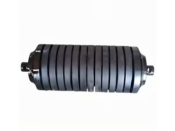
Rollers for conveyor belt loading zones operate under very different conditions from ordinary carrying idlers installed farther along the conveyor. At a transfer or feeding point, bulk material can fall onto the moving belt with considerable impact. Instead of experiencing only the steady weight of the belt and conveyed material, the supporting rollers may also receive short-duration dynamic forces as each load enters the system.
This is why loading zones often require buffer or impact-oriented rollers rather than simply repeating the same roller configuration used throughout the rest of the carrying section. The objective is to support the belt while reducing the direct effect of falling material on the belt surface, roller structure, bearings, and surrounding idler frame.
A suitable loading-zone roller still depends on basic engineering factors such as roller diameter, length, bearing arrangement, shaft geometry, sealing, material, and conveyor alignment. However, these parameters need to be evaluated together with material drop conditions, loading distribution, particle size, contamination, and the physical layout of the transfer point.
Why Loading Zones Need Different Rollers
The loading point is where conveyed material first reaches the belt. When material falls from a chute or upstream conveyor, the vertical component of its movement creates an impact force in addition to the normal static load.
The belt absorbs part of this impact before transmitting the remaining force into the rollers and idler structure underneath. If the support system is not suitable for this operating condition, repeated impact can contribute to belt deformation, roller damage, bearing stress, frame vibration, or uneven belt contact.
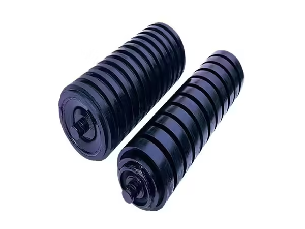
The existing Buffer Roller is specifically designed for belt conveyors where material impact needs to be reduced. Instead of treating a loading point as an ordinary carrying section, the roller structure places greater emphasis on buffering and belt protection.
This distinction is important because rollers for conveyor belt systems should be selected according to their exact position rather than from one general specification applied across the complete conveyor.
How Material Impact Reaches the Roller
In a conveyor belt, transported material normally moves horizontally after it has stabilized on the belt. At the loading point, however, material may also be moving vertically or at another angle as it leaves the chute.
When that material contacts the belt, kinetic energy is transferred into the belt and supporting structure. The severity of this event depends on several factors, including drop height, particle mass, material distribution, belt speed, loading angle, and the amount of support beneath the impact area.
A large piece of rock falling through a significant height creates a very different mechanical condition from fine material entering the belt through a controlled low-height chute. The roller specification should therefore be based on the real loading process rather than only on belt width.
Buffer Rollers Versus Standard Carrying Rollers
A standard carrying roller is primarily intended to support the belt and conveyed load after the material has entered a relatively stable transport condition. A buffer roller performs the same basic support function but is specifically designed for a position where impact needs additional attention.
The difference is therefore not simply outside diameter or length. Buffer roller construction and material choices are intended to provide additional protection around the loading zone.
This does not mean every carrying position requires a buffer roller. Once the conveyed material has stabilized and the dynamic impact has been reduced, conventional carrying idlers may be more appropriate for the remaining conveyor length.
A well-designed conveyor divides the belt path into functional zones instead of assuming that every supporting roller performs exactly the same duty.
Roller Diameter in Loading-Zone Applications
The current Buffer Roller range includes common diameters of approximately 89, 108, 133, and 159 mm. These diameters are available with different roller lengths and bearing arrangements so the component can be matched with different conveyor structures.
Diameter should be considered together with the idler bracket, belt width, shaft design, and roller spacing. Simply choosing the largest diameter does not automatically create the most suitable loading-zone support.
Changing diameter can also change the belt line if the existing frame was designed around another roller size. For replacement applications, maintaining compatibility with neighboring idlers is therefore especially important.
The roller should fit the complete support geometry rather than forcing the conveyor structure to adapt to an otherwise incompatible component.
Roller Length Must Match the Impact Area
Buffer rollers are available in a broad range of lengths because different conveyor widths and idler arrangements require different support spans. The current product range includes lengths from relatively short rollers around 190 mm through configurations extending to approximately 1600 mm depending on roller diameter.
The appropriate length should reflect the actual idler structure. In a troughing set, several rollers may share the belt-support width, while another arrangement may use longer individual components.
The loading pattern also deserves attention. If material repeatedly enters the conveyor toward one side rather than near the center, the resulting load distribution can become uneven even when the roller length matches the nominal belt width.
Roller length therefore needs to be evaluated together with chute position and material flow.
Bearing Selection Remains Important Under Impact
Buffering does not eliminate load transmission through the roller. The force still moves from the outer structure through the bearing arrangement and shaft into the supporting frame.
The current Buffer Roller range uses different bearing models according to roller diameter. For example, Φ89 mm configurations are associated with 204 bearings, Φ108 mm with 205, Φ133 mm with 305, and Φ159 mm configurations can use 306 or 308 arrangements.
These bearing relationships illustrate why component selection should remain system-based. Roller diameter, shaft size, bearing housing, bearing, and seal structure all need to correspond with one another.
A bearing should not be changed independently without confirming that the surrounding roller components remain dimensionally compatible.
Shaft Geometry Transfers Impact Into the Frame
The shaft creates the fixed mechanical connection between the rotating roller and conveyor frame. Forces entering through the belt and roller body ultimately pass through the bearing system and into the shaft.
Shaft diameter, material, overall length, and end geometry should therefore match the roller design and supporting bracket. Flats or other end features also need to maintain the correct relationship with the installation structure.
At loading points, frame condition becomes equally important. A strong shaft cannot compensate for a damaged bracket or poorly seated mounting position.
Roller and frame should therefore be inspected together when repeated impact-related problems appear in the same conveyor location.
Sealing Matters in Loading Zones
Transfer points frequently create large amounts of dust and loose material. Fine particles can accumulate around the roller ends where the shaft, bearing housing, and sealing components are located.
This makes sealing particularly important in loading-zone rollers. The seal needs to limit contamination entering toward the bearing chamber while maintaining suitable clearances for normal rotation.
The wider conveyor roller range supports several sealing configurations and bearing arrangements for different industrial environments. The appropriate structure should be selected according to both roller geometry and actual contamination conditions.
Heavy dust exposure should therefore be included in the original roller specification instead of being treated only as a maintenance issue after operation begins.
Why Material Distribution Matters
Impact severity is not determined only by the total amount of material entering the conveyor. Where that material lands across the belt can be equally important.
A centered and controlled material stream allows the impact load to be distributed more evenly across the supporting idler structure. Material consistently entering one side can concentrate load on one side roller and also influence belt tracking.
When a loading-zone roller repeatedly develops problems, technicians should therefore inspect the chute and material stream as well as the roller itself.
Replacing the component without correcting uneven material distribution can expose the new roller to exactly the same mechanical conditions.
Drop Height Influences Impact Severity
Material falling through a greater vertical distance reaches the belt with higher velocity. This increases the dynamic force generated during contact and can change the requirements of the supporting structure.
Reducing uncontrolled drop height through appropriate transfer-point design can therefore complement the use of buffer rollers. The roller should not be expected to compensate indefinitely for an unnecessarily severe material drop.
This is an important system-level principle. Effective loading-zone design combines suitable rollers with controlled material transfer, appropriate belt support, frame geometry, and maintenance.
The best roller specification cannot correct every problem created elsewhere in the transfer system.
Large Particles Create Concentrated Loads
Bulk material is not always distributed as a smooth continuous stream. Mining and quarry applications can include larger individual particles that create localized impact when they reach the belt.
A concentrated impact acts differently from the same total mass distributed evenly across a wider area. The belt and one or two rollers may receive much of the load before surrounding components become involved.
For this reason, particle-size distribution can be relevant when evaluating rollers for conveyor belt loading zones.
Where larger material is common, the support arrangement should be reviewed according to the actual transfer conditions rather than a nominal average load alone.
Buffer Rollers in Coal Handling
Coal conveyors commonly use long belt systems with dedicated loading and transfer points. Although coal characteristics vary, these environments can generate dust and repeated impact as material moves between sections of the handling system.
Buffer rollers can be positioned beneath the belt where incoming material needs additional support. Their role is to reduce the direct effect of loading impact while continuing to provide stable belt contact.
Dust around the roller ends also makes sealing and maintenance important. Material buildup should be removed before it prevents technicians from observing the actual condition of the shaft and sealing area.
Loading-zone maintenance should therefore combine roller inspection with chute and surrounding structure inspection.
Buffer Rollers in Quarry Conveyors
Quarry applications create particularly clear examples of why impact-oriented rollers are useful. Stone and aggregate can enter the belt from crushers, screens, or transfer chutes, sometimes with relatively large individual particles.
The roller arrangement beneath these points needs to support dynamic loading while maintaining the intended belt path.
Repeated impact can also loosen material around brackets or cause buildup that changes the geometry of the support structure. Regular inspection should therefore include frame alignment and material accumulation as well as roller condition.
Once the material has stabilized farther along the conveyor, conventional carrying rollers can resume the main support function.
Buffer Rollers in Cement and Processing Plants
Cement-related applications create another challenge because loading impact may occur together with fine airborne dust.
In these environments, the external buffering function and internal bearing protection need to work simultaneously. A roller that handles impact effectively can still develop bearing problems if dust repeatedly enters around an unsuitable or damaged sealing system.
This demonstrates why buffer roller selection should not focus on one visible feature alone.
Roller diameter, bearing structure, shaft geometry, sealing, material, surface condition, and installation position all remain part of the complete design.
Corrosive Operating Environments
The Buffer Roller product range is also intended for demanding environments such as coal washing, coking, and chemical-related applications where corrosion resistance can become an important operating factor.
Environmental exposure should be considered separately from impact load. A roller may need to resist both dynamic mechanical forces and surrounding moisture or chemical contamination.
Material and surface configuration should therefore reflect the complete operating environment rather than only the loading mechanism.
This is particularly important for long-term installations where repeated exposure occurs throughout normal production.
Flame Retardancy and Antistatic Requirements
Certain industrial environments can impose additional requirements related to flame retardancy and static behavior. These characteristics are particularly relevant where conveyed materials or operating environments make ignition control more important.
The current Buffer Roller description identifies flame-retardant and antistatic properties as part of its application characteristics.
Such requirements should be defined at the project level rather than assumed to apply equally to every conveyor. The roller material and structure need to match the safety and operating requirements of the actual installation.
Engineering specifications should therefore include environmental and operational conditions alongside dimensions.
Roller Spacing in an Impact Zone
Roller spacing affects how much belt area is unsupported between adjacent idlers. In a normal carrying section, spacing is selected according to belt characteristics and load distribution. In a loading area, the higher dynamic forces can require closer attention to support density.
The objective is to prevent excessive local belt deflection while distributing impact through an appropriate number of supporting components.
Spacing should be evaluated together with the buffer roller arrangement rather than simply copied from a straight carrying section.
If the belt deflects excessively between rollers, increasing the nominal strength of one individual roller may not address the real support problem.
Frame Rigidity Is Part of Buffer Performance
A buffer roller operates through the idler frame and conveyor structure beneath it. If the frame flexes excessively, is damaged, or has become misaligned, the roller cannot maintain the intended relationship with the belt.
Loading points should therefore be inspected for bracket deformation, loose fasteners, uneven mounting surfaces, and accumulated material.
A repeated roller problem in exactly the same position often deserves a frame inspection before another replacement is installed.
System reliability depends on the load path from belt to roller, from roller to shaft, and from shaft into the supporting structure.
How Buffer Rollers Differ From Parallel Rollers
Parallel rollers primarily support and guide the belt in upper or lower conveyor positions. Buffer rollers are intended specifically for zones where material impact needs to be reduced.
The two products may share some basic diameter and bearing relationships, but their intended duty differs.
This distinction matters because rollers should be selected according to operating function rather than visual similarity. A component that physically fits a bracket is not automatically appropriate for the load condition occurring at that location.
The correct question is therefore not simply whether one roller can replace another, but whether its design matches the mechanical duty at that conveyor position.
How Buffer Rollers Differ From Standard Conveyor Rollers

Standard conveyor rollers cover a broad range of carrying and return applications. They can use multiple diameters, lengths, bearing arrangements, materials, seals, and idler structures.
Buffer rollers form a more specialized branch within this broader roller family. Their purpose is to provide additional protection where incoming material produces dynamic impact.
This specialization means their value is highest when they are installed at positions that genuinely require buffering.
Using them throughout an entire conveyor without an engineering reason is different from strategically positioning them at loading and transfer points.
A Practical Loading-Zone Specification
A loading-zone roller specification should connect material conditions with roller construction.
| Specification Area | What to Confirm |
|---|---|
| Conveyor position | Loading or transfer zone |
| Belt width | Match idler geometry |
| Material | Type, particle size, distribution |
| Drop condition | Height and loading direction |
| Roller diameter | Match frame and operating duty |
| Roller length | Match belt and idler set |
| Bearing | Match diameter and load path |
| Shaft | Match bearing and bracket |
| Seal | Match dust and moisture exposure |
| Environment | Corrosion, dust, safety requirements |
| Frame | Alignment and rigidity |
| Roller spacing | Support around impact zone |
Reviewing these parameters together provides a stronger basis than selecting a buffer roller only by outside diameter.
Inspection After Installation
After new rollers for conveyor belt loading zones are installed, their relationship with the belt and surrounding frame should be observed during actual material loading.
Technicians should look for uneven belt contact, excessive movement, abnormal noise, vibration, material buildup, or differences between neighboring rollers.
The loading stream should also be observed. If material strikes one side of the belt consistently, the mechanical condition should be corrected before the resulting asymmetrical load becomes a repeated maintenance problem.
An installation check under real operating conditions provides information that cannot always be obtained from static measurements alone.
Routine Maintenance of Buffer Rollers
Routine maintenance should focus on both impact-related and conventional roller symptoms.
Rollers should rotate freely without abnormal noise or visible runout. Seals should remain intact, and accumulated material around the roller ends should not be allowed to hide bearing-area problems.
Surface damage should also be monitored because loading-zone rollers can experience repeated contact with material through the moving belt.
Comparing several neighboring rollers helps determine whether a developing issue belongs to one component or to the complete loading area.
When Repeated Roller Failure Indicates a System Problem
If rollers repeatedly develop problems at the same transfer point, replacing the component alone may not address the real cause.
Possible contributing factors include excessive drop height, off-center material loading, damaged idler frames, unsuitable roller spacing, persistent contamination, belt tracking issues, or a roller specification that does not match the operating duty.
Maintenance records can be useful because they reveal whether the same location experiences recurring problems across several replacement cycles.
A repeated pattern should trigger investigation of the loading system rather than another isolated roller diagnosis.
Common Mistake: Using Standard Rollers at Every Position
Using one roller specification throughout an entire conveyor can simplify inventory, but it may ignore genuine differences between operating zones.
A loading point can create impact conditions that do not exist farther along the carrying section. The support structure should therefore reflect that difference where necessary.
The objective is not to make every conveyor position unique. It is to recognize when operating conditions are sufficiently different that another roller structure is justified.
Buffer rollers provide one example of this position-specific approach.
Common Mistake: Selecting Only by Belt Width
Belt width helps determine roller length and idler geometry, but it provides little information about impact severity.
Two conveyors with the same belt width can handle completely different materials, drop heights, particle sizes, and loading arrangements.
One may require ordinary carrying rollers, while another may need additional buffering around the loading point.
Belt width should therefore be treated as one dimensional input within a broader application specification.
Common Mistake: Ignoring the Transfer Chute
A roller problem can begin above the belt rather than below it.
An incorrectly positioned chute can cause material to fall from excessive height or consistently strike one side of the belt. These conditions change the load received by the rollers regardless of their specifications.
When loading-zone rollers develop uneven wear or repeated problems, the material-transfer path should therefore be inspected together with the idlers.
Improving the material trajectory can sometimes reduce stress across the complete support system.
Conclusion
Rollers for conveyor belt loading zones need to be selected according to the dynamic conditions created when material enters the conveyor. Buffer rollers are specifically designed for this position because their primary role is to reduce the effect of material impact on the belt and supporting roller structure.
The correct configuration still depends on conventional roller engineering factors such as diameter, length, bearing arrangement, shaft geometry, sealing, frame compatibility, and environmental exposure. The current Buffer Roller range includes Φ89, 108, 133, and 159 mm configurations with multiple lengths and corresponding bearing options, allowing the structure to be matched with different conveyor layouts.
Successful loading-zone design also requires attention beyond the roller itself. Drop height, material distribution, particle size, roller spacing, chute position, frame rigidity, contamination, and maintenance all influence the forces acting on the support system.
When these factors are considered together, buffer rollers become part of a controlled impact-management system rather than simply a stronger replacement for ordinary conveyor rollers.
FAQ
What rollers for conveyor belt systems are suitable for loading zones?
Loading and transfer zones often use buffer or impact-oriented rollers because incoming material creates dynamic forces that differ from normal carrying conditions. The correct roller still needs to match belt width, idler geometry, shaft structure, bearing arrangement, sealing, material characteristics, drop conditions, and the surrounding conveyor frame.
What is the main purpose of a buffer roller?
A buffer roller is designed to reduce the impact transferred from falling material through the conveyor belt into the supporting roller and idler structure. It is primarily used around loading and transfer areas where dynamic forces are more significant than along stable carrying sections of the conveyor.
What diameters are available for Buffer Rollers?
The current Buffer Roller range includes common diameters of approximately 89, 108, 133, and 159 mm. Each diameter can be combined with several roller lengths and corresponding bearing arrangements, allowing the roller to be matched with different belt widths, idler structures, and loading-zone requirements.
Why do buffer rollers still need good seals and bearings?
Impact protection does not remove the conventional mechanical requirements of a conveyor roller. Bearings still provide the rotational interface between the roller and shaft, while seals protect the bearing area from dust, moisture, and other contaminants. Loading zones can generate substantial dust, making internal protection particularly important.
What should be checked when buffer rollers repeatedly develop problems?
Repeated problems should trigger inspection of the complete loading zone, including drop height, material trajectory, chute position, belt tracking, roller spacing, idler-frame alignment, contamination, and neighboring rollers. When failures repeatedly occur at the same location, the surrounding conveyor conditions may be contributing more than the individual roller itself.
 English
 French
 Spanish