

Table of Contents
Introduction
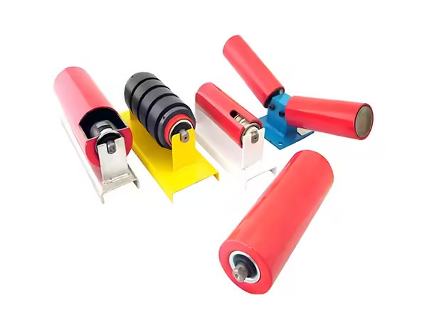
A roller idler conveyor relies on repeated rotating support points to maintain the path of the belt and transfer belt loads into the conveyor structure. Among the different idler configurations used in industrial systems, parallel rollers provide a relatively simple support geometry, but their performance still depends on accurate dimensions, stable bearings, effective sealing, controlled runout, and correct installation.
Parallel rollers are commonly divided into upper and lower roller positions. Although both use a cylindrical roller structure, their operating conditions are not necessarily identical because the upper side may interact with loaded or guided sections of the belt while the lower side can operate along the return path. Belt width, roller spacing, environmental contamination, shaft geometry, and frame alignment therefore need to be considered together.
This guide focuses specifically on parallel rollers used in roller idler conveyor systems. It explains how diameter, roller length, tube structure, bearings, seals, rotational resistance, axial movement, radial runout, and conveyor position influence the final roller configuration.
What Is a Parallel Roller in a Roller Idler Conveyor?
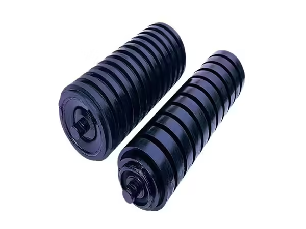
A parallel roller is a cylindrical idler installed so that its rotational axis remains generally perpendicular to the direction of belt movement and parallel with other rollers positioned across the same conveyor section. Depending on the system design, it can operate as an upper or lower support roller.
The current Parallel Roller range includes several dimensions matched with different belt widths. Typical configurations include Φ89 and Φ108 mm rollers, while larger diameter options are available for applications requiring different structural dimensions.
The basic operating principle remains straightforward. The belt travels across the rotating roller shell while the central shaft remains supported by the frame. Bearings allow the tube to rotate around the shaft, and sealing components help protect the internal bearing area from environmental contamination.
Although the structure appears simple, successful operation depends on the dimensional relationship between all of these parts.
Upper and Lower Parallel Rollers Have Different Roles
Parallel rollers can be divided into upper and lower configurations according to their position in the conveyor system. The upper roller supports and guides the belt along its working path, while the lower roller is commonly associated with belt return support.
These positions should not automatically use identical specifications. The upper side can experience different belt loading, contamination, and structural forces from the return side. Material remaining on the belt can also affect lower rollers even after the main conveyed load has been discharged.
The most suitable roller idler conveyor design therefore identifies the operating position first and then defines roller diameter, length, shaft dimensions, bearings, and sealing around that function.
This position-based approach provides a stronger engineering basis than treating every parallel roller as an interchangeable cylindrical component.
How a Parallel Roller Supports the Belt
In a conveyor belt, the belt needs continuous support as it travels between loading, carrying, discharge, and return sections. Parallel rollers create rotating support surfaces that reduce direct sliding contact between the belt and the conveyor structure.
As belt load reaches the roller surface, the force passes through the tube toward the internal bearings. The bearings transfer this load into the shaft, which then passes it into the supporting frame.
This load path means every major roller component contributes to the final mechanical behavior. Increasing tube thickness cannot compensate for an unsuitable shaft, while a large bearing cannot correct poor housing alignment.
The complete roller therefore needs to be specified as one connected structure.
Roller Diameter Changes More Than External Size
Parallel roller diameters commonly include 89, 108, 133, and 159 mm configurations. Diameter affects the external belt-contact surface but also influences the available internal space for bearing housings, seals, bearings, and shaft-related components.
A larger roller should not automatically be interpreted as the correct choice for a larger conveyor. Belt width, loading conditions, roller spacing, frame dimensions, bearing arrangement, and installation geometry also influence the appropriate diameter.
When an existing conveyor is being maintained, changing roller diameter can alter the belt line relative to neighboring idlers. Even a mechanically strong roller can therefore create an installation problem if its external dimensions change the intended support geometry.
Diameter selection should always remain connected with the surrounding conveyor structure.
Roller Length Must Match Belt Width and Frame Geometry
Parallel roller length is closely related to belt width because the roller needs to provide appropriate support across the intended belt section.
The existing product range includes roller lengths from approximately 600 to 1600 mm. For example, Φ89 mm rollers can be configured in several lengths, while Φ108 mm configurations can extend to longer dimensions for wider belts.
However, belt width alone should not determine the final length. Shaft projection, bracket spacing, working roller length, and total installed dimensions also need to be considered.
A replacement roller can match the nominal belt width but still fail to fit correctly if its shaft-end dimensions differ from the existing frame.
This is why dimensional drawings should identify both roller-body length and complete installation geometry.
Tube Material Influences Roller Behavior
Parallel roller tubes can use different materials according to the intended application. The current product range includes Q235 steel as well as selected polymer and rubber-related configurations.
Material selection affects structural behavior, mass, wear, corrosion characteristics, and the manufacturing route used to produce the roller.
Steel tubes are common in demanding industrial applications because they provide a predictable structural base for bearing housings and internal roller components. Other materials can be suitable when their physical characteristics match the intended operating environment.
The material should therefore be selected according to belt load, conveyed material, contamination, environmental exposure, and roller dimensions rather than treated as an isolated preference.
Tube Wall Thickness Needs Structural Consistency
The Parallel Roller product range includes tube-wall thicknesses around 2.0–3.0 mm depending on the configuration.
Wall thickness influences the stiffness of the rotating shell and its ability to maintain geometry under load. However, simply increasing wall thickness does not guarantee a better roller because the shaft, bearing housing, bearings, and overall assembly also contribute to the load path.
A roller idler conveyor should therefore be evaluated as a complete system. If another component becomes the limiting factor, adding additional tube material may provide limited practical benefit.
The objective is dimensional and mechanical balance rather than maximizing one specification independently.
Bearings Determine the Rotational Interface
The bearing allows the roller tube to rotate relative to the stationary shaft. Its internal clearance, dimensions, condition, and installation therefore influence rotational resistance and overall roller behavior.
Parallel roller configurations use deep-groove ball bearings matched with the shaft and housing structure. Bearing selection should account for roller diameter, shaft size, loading requirements, and the intended operating environment.
The bearing should not be treated as a separate component that can be changed without reviewing the rest of the assembly. Increasing bearing size can require changes to the bearing housing, shaft, and seal.
A properly matched system keeps these components dimensionally compatible from the beginning.
Sealing Protects the Bearing Area
Parallel rollers frequently operate in environments where dust, moisture, fine particles, or conveyed material can reach the roller ends. The seal therefore forms an important protective structure between the external environment and the bearing chamber.
The product configuration uses a combined sealing system incorporating internal sealing, labyrinth sealing, and external protection. Nylon 6 and nitrile rubber are among the materials used in the sealing structure.
A seal is only effective when its dimensions match the shaft and bearing housing. Incorrect clearances can reduce protection or create unnecessary interference with rotating components.
Environmental information should therefore form part of the roller specification rather than being considered only after contamination problems appear.
Rotational Resistance Matters Across Large Conveyor Systems
The Parallel Roller specification lists rotational resistance of no more than approximately 2.5 N.
For one individual roller, a small change in rotational resistance may appear relatively minor. A long conveyor, however, can contain many idlers operating simultaneously, which means repeated resistance across multiple rollers can influence the mechanical behavior of the overall system.
Bearing condition, seal structure, alignment, contamination, and assembly accuracy all influence how freely the roller rotates.
This makes rotational resistance useful as a final assembled-roller characteristic because it reflects the combined condition of several internal components rather than only one part.
Axial Movement Should Remain Controlled
The listed axial movement for the Parallel Roller is no more than approximately 0.7 mm.
Axial movement describes the amount of longitudinal displacement that can occur within the roller assembly. Excessive movement can indicate unsuitable internal clearances or an issue with the relationship between the shaft, bearing, housing, and retaining structure.
The appropriate limit needs to be considered as part of the roller design rather than corrected by tightening components indiscriminately.
A stable assembly needs enough dimensional control to maintain the intended internal positions while still allowing the roller to rotate normally.
This balance is established through component manufacturing and assembly accuracy.
Radial Runout Influences Belt Contact
The Parallel Roller specification lists radial runout of no more than approximately 0.5 mm.
Runout describes variation in the position of the outer roller surface as the component rotates. A roller with excessive runout repeatedly changes its contact relationship with the moving belt during every revolution.
Tube straightness, bearing housing alignment, shaft geometry, bearing installation, and assembly can all influence the final runout.
Because several manufacturing stages contribute to this measurement, runout provides a useful final indicator of overall roller geometry.
In a roller idler conveyor containing many parallel rollers, maintaining similar runout characteristics across a batch supports more consistent belt contact.
Load Capacity Must Be Interpreted With the Application
The Parallel Roller product specification lists load capacity of at least approximately 20 kN for the applicable configuration.
This value should not be used by itself to determine suitability for every conveyor. Actual load distribution depends on belt width, roller spacing, material distribution, conveyor geometry, installation position, and dynamic operating conditions.
A roller in a relatively stable section can experience different forces from one near a loading or transfer zone.
The complete conveyor structure should therefore be evaluated before applying one nominal roller specification across every position.
Load capacity is one part of the design envelope, not a replacement for application engineering.
Surface Treatment Protects Exposed Steel
Steel rollers can use electrostatic spraying to create an external protective coating. The current Parallel Roller specification lists a paint-film thickness of at least approximately 90 μm.
Surface treatment protects exposed steel surfaces from the surrounding environment, but it should not be confused with bearing sealing.
The coating acts on the external metal structure, while the internal seal protects the bearing area around the shaft. These two protective systems address different environmental paths.
Industrial roller design therefore needs to consider both. Improving the external coating does not eliminate the need for effective sealing, and a strong sealing system does not protect every exposed steel surface.
Parallel Rollers for Bulk Material Conveyors
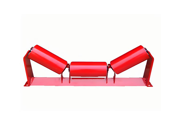
Parallel rollers can be used in conveyor systems transporting materials such as coal and ore where stable belt support is required along defined sections.
These applications can expose rollers to dust, vibration, abrasive contamination, and continuous operation. Bearing protection and manufacturing consistency therefore become important alongside structural dimensions.
Material buildup should also be monitored because contamination on the roller surface can change the effective contact geometry between the belt and roller.
For large bulk-material systems, batch consistency becomes increasingly important because the same roller configuration may be repeated across many support positions.
Parallel Rollers for Unit-Load Conveyors
Parallel roller structures can also support conveyor sections handling boxed or unitized goods, depending on the conveyor design.
The loading behavior in these systems differs from loose bulk-material transport because forces can be concentrated around the contact positions created by individual items.
Roller length, spacing, support geometry, and surface condition should therefore be considered in relation to the transported goods.
This illustrates why the same basic cylindrical roller can appear in different industrial environments while requiring different overall system design.
Roller Spacing Affects Individual Roller Load
Idler spacing determines how much belt length is supported by each roller position. Increasing the distance between supporting rollers changes the unsupported belt span and can alter the load acting on individual components.
Spacing should therefore be determined according to belt characteristics, material loading, conveyor position, and structural design.
A roller with suitable nominal load capability can still operate under unsuitable conditions if the surrounding conveyor geometry transfers more force to it than intended.
When repeated roller problems occur across one conveyor section, spacing and frame arrangement should be inspected alongside the roller itself.
Shaft Geometry Connects the Roller to the Frame
The shaft transfers load from the bearings into the conveyor structure and determines how the roller mounts into the frame.
Shaft diameter needs to match the bearing arrangement, while shaft-end geometry needs to correspond with the supporting bracket. Flats, grooves, or other machined features can be required depending on the installation.
When replacement rollers are specified, shaft dimensions deserve the same attention as roller diameter and length.
A roller can have the correct outer dimensions but still be impossible to install correctly if the shaft does not match the existing mounting structure.
Why Parallel Roller Alignment Matters
Parallel rollers are expected to maintain a predictable geometric relationship with the belt and neighboring idlers. A twisted bracket, incorrectly seated shaft, or damaged conveyor frame can change this relationship even when the roller itself is manufactured correctly.
Alignment checks should therefore examine several consecutive positions rather than looking only at one component.
If one roller sits noticeably higher or at another angle, the belt can contact it differently from adjacent rollers. Replacing the roller without checking the bracket may leave the original problem unresolved.
Stable roller idler conveyor operation depends on both component accuracy and structural installation.
Manufacturing Accuracy Begins With the Tube
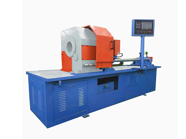
Roller manufacturing begins with tube preparation. Tube diameter, straightness, wall structure, and length establish the geometry that later internal components need to follow.
After cutting, bearing housings are positioned relative to the tube ends, while shafts, bearings, and seals establish the internal rotational structure.
If tube geometry varies significantly before assembly, later processes need to compensate for an unstable starting component.
Controlled manufacturing therefore builds the finished roller through a sequence of dimensional references rather than relying entirely on final inspection.
Bearing Housing Position Affects Final Runout
Bearing housings at opposite ends should remain aligned around the intended roller axis.
If one housing is positioned off-center, the bearing and shaft relationship can change, producing runout even if the tube itself is straight.
Assembly fixtures and controlled positioning help maintain concentricity during production.
This is particularly important for parallel rollers because their simple external geometry can make internal alignment problems easy to overlook until the completed roller is rotated.
Final runout measurement provides a useful verification that the internal structure has been assembled correctly.
Inspection Before Installation
A completed parallel roller should be checked before installation so obvious dimensional or rotational problems are not transferred into the conveyor.
Useful checks include roller diameter, overall length, shaft geometry, visible surface condition, rotation, axial movement, and runout where required.
The component should then be compared with the intended frame position so mounting dimensions can be confirmed.
For replacement work, neighboring rollers can provide useful dimensional references, but technical drawings remain preferable when available.
This inspection step helps distinguish product geometry from installation problems before the conveyor returns to operation.
Maintenance Inspection in Service
Once installed, parallel rollers should be monitored for changes in rotation, noise, vibration, surface buildup, seal condition, and alignment.
A roller that becomes difficult to rotate may have bearing, sealing, contamination, or internal alignment problems. Visible runout can indicate external deformation or changes within the bearing structure.
Material accumulation should also be removed where it interferes with inspection because debris can hide seal damage or change belt contact.
Maintenance should compare symptoms across neighboring rollers to determine whether the issue is isolated or associated with a wider conveyor section.
Common Mistake: Selecting Only by Roller Diameter
Outside diameter is easy to measure, but it does not identify the complete roller.
Two Φ108 mm rollers can use different lengths, shafts, bearings, seals, wall structures, or mounting arrangements. Their external similarity does not guarantee installation compatibility.
A correct replacement specification should therefore include roller-body length, shaft dimensions, bearing arrangement, and installation geometry.
This becomes particularly important when rollers are being fitted into existing conveyor frames that cannot easily be modified.
Common Mistake: Ignoring Upper and Lower Positions
Upper and lower parallel rollers can appear similar, but their operating environment and belt interaction may differ.
Using one specification everywhere without checking conveyor position can overlook differences in load, contamination, return-belt behavior, and support geometry.
The position should therefore be identified before final roller specifications are confirmed.
This does not mean every conveyor requires completely different upper and lower rollers. It means that any decision to use the same structure should come from engineering compatibility rather than assumption.
Common Mistake: Replacing a Roller Without Checking the Frame
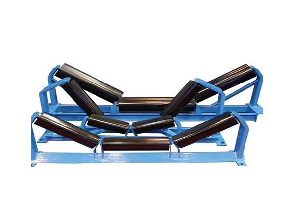
Repeated failure at the same conveyor position can indicate a problem with alignment, support geometry, material buildup, or loading rather than repeated defects in individual rollers.
Installing another identical component may temporarily restore operation while leaving the surrounding cause unchanged.
Maintenance teams should therefore inspect the shaft seating area, bracket geometry, neighboring idlers, belt path, and material distribution whenever the same position produces recurring problems.
This system-level approach reduces the risk of diagnosing every conveyor symptom as an isolated roller issue.
How to Specify a Parallel Roller
A useful parallel roller specification should combine external dimensions with internal structure and application information.
| Specification Area | Information to Confirm |
|---|---|
| Conveyor position | Upper or lower |
| Belt width | Match support geometry |
| Roller diameter | 89, 108, 133, 159 mm or required size |
| Roller length | Match belt and frame |
| Tube material | Steel or applicable alternative |
| Shaft | Diameter and mounting geometry |
| Bearing | Match load and housing |
| Seal | Match bearing and environment |
| Runout | Confirm finished roller geometry |
| Surface treatment | Match external environment |
This approach gives manufacturing and maintenance teams a clearer technical reference than simply describing the component as a standard conveyor roller.
Conclusion
A roller idler conveyor using parallel rollers depends on the relationship between simple external geometry and carefully controlled internal components. Roller diameter and length determine the basic support structure, while shafts, bearings, bearing housings, seals, tube construction, and surface treatment determine how the completed roller operates.
Performance should also be evaluated through assembled characteristics such as rotational resistance, axial movement, and radial runout. These measurements reflect the combined condition of several components and help verify that the finished roller behaves as one controlled mechanical assembly.
Upper and lower positions, belt width, roller spacing, frame alignment, loading conditions, and environmental contamination all influence the final specification. For this reason, parallel rollers should be matched with the actual conveyor rather than selected by diameter alone.
FAQ
What is a parallel roller in a roller idler conveyor?
A parallel roller is a cylindrical non-driven roller used to support and guide the conveyor belt while remaining aligned with other supporting rollers in the conveyor structure. Parallel rollers can be used in upper or lower positions, with their dimensions, shaft structure, bearings, seals, and mounting geometry matched to the actual conveyor application.
What diameters are available for parallel conveyor rollers?
Typical Parallel Roller configurations include diameters of approximately 89, 108, 133, and 159 mm. The suitable diameter depends on belt width, roller length, loading conditions, shaft geometry, bearings, roller spacing, and the existing conveyor frame rather than simply selecting the largest available diameter.
Why is radial runout important for a parallel roller?
Radial runout indicates how consistently the outer roller surface follows the intended rotational axis. Excessive runout can change belt contact during every revolution. Tube geometry, bearing housing position, shaft alignment, bearings, and assembly can all influence the final measurement, making runout a useful indicator of overall roller manufacturing consistency.
How do seals affect parallel roller operation?
Seals help protect the internal bearing area from dust, moisture, and other contaminants entering around the roller ends. The seal must match the shaft, bearing housing, and bearing structure while maintaining suitable internal clearances. Industrial conveyors operating in dusty or exposed environments require particular attention to sealing compatibility.
What should be checked when replacing a parallel roller?
Replacement checks should include roller diameter, body length, overall shaft length, shaft-end geometry, bearing arrangement, sealing structure, upper or lower installation position, belt width, and supporting bracket dimensions. The frame and neighboring rollers should also be inspected when repeated problems occur at the same conveyor position.
 English
 French
 Spanish