

Table of Contents
Introduction

A roll milling machine used in conveyor roller production has a very specific task: machining controlled flat surfaces at both ends of a roller shaft. These flats are not decorative features. They influence how the finished shaft fits into supporting brackets, how consistently rollers can be installed, and whether corresponding features at opposite ends maintain the geometry defined by the roller drawing.
For batch roller manufacturing, producing these surfaces one end at a time can introduce repeated positioning and clamping variables. A dedicated double-end milling structure addresses this problem by locating the shaft once and machining corresponding surfaces at both ends within the same production cycle.
This article focuses specifically on the use of a roll milling machine for conveyor roller shaft flat machining. It explains the machine structure, workpiece range, double-end processing principle, tooling, hydraulic control, setup, inspection, and its relationship with other shaft-processing stages in conveyor roller manufacturing.
What Is a Roll Milling Machine in Roller Production?
In this application, a roll milling machine refers to dedicated milling equipment used to machine flat grooves or flat surfaces on the ends of conveyor roller shafts. It should not be confused with equipment used to roll sheet metal or with a conventional rolling mill.
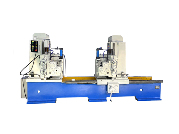
The existing Automatic Roller Shaft Double End Flat Slot Milling Machine is designed specifically for belt conveyor roller shafts. Its TX-2023 configuration can machine shaft diameters of approximately Φ20–40 mm and lengths from 260 to 2300 mm, with flat widths from 6 to 35 mm and milling depths from 0 to 5 mm.
The machine can process four surfaces across both shaft ends within one setup. This makes the equipment particularly suitable for repetitive roller shaft production where the relative position of corresponding flats needs to remain stable from one component to the next.
Why Roller Shafts Need Flat Milling
A round shaft provides a strong and simple central support for a conveyor roller, but many conveyor mounting structures require controlled flats at the shaft ends. These flats can help locate the shaft in the supporting bracket and prevent unwanted rotational movement at the mounting position.
Their geometry therefore needs to correspond with the conveyor frame rather than simply being machined to an approximate shape. Flat width, depth, position, and orientation can all influence how the finished roller fits into the installation.
If the two ends are machined separately without a stable common reference, the corresponding flats may differ slightly in position or orientation. For individual components this variation may appear small, but in a conveyor containing many similar rollers, repeated differences can affect installation consistency.
A dedicated roll milling machine is therefore designed around the geometry of the shaft rather than around general-purpose surface machining.
Double-End Milling Reduces Repositioning
One of the main characteristics of the TX-2023 machine is its ability to process both shaft ends within the same setup. Instead of machining one side, removing the shaft, reversing it, locating it again, and then processing the second end, the machine positions the complete shaft between two machining units.
This arrangement reduces the number of times the workpiece needs to be re-established against a new reference. Both ends remain related to the same shaft centerline and clamping structure while corresponding flats are produced.
The advantage is particularly important when four flat surfaces need to be machined across two ends. The machine can complete these features within a coordinated cycle rather than treating each individual surface as a separate manual operation.
Double-end milling does not eliminate the need for inspection, but it removes unnecessary workpiece handling from the production sequence.
How Milling Creates the Shaft Flat
Milling removes material using a rotating cutting tool while controlled relative movement occurs between the cutter and workpiece. In roller shaft production, the cutter removes material from selected areas of the round shaft to create the specified flat geometry.
The cutting process needs to maintain a controlled relationship between cutter position, workpiece centerline, and required milling depth. If the shaft is positioned differently between workpieces, the resulting flat depth or width can also change even when the machine setting remains unchanged.
For this reason, milling accuracy begins with workpiece locating and clamping. The cutting tool can only reproduce the desired geometry when the shaft enters the machine in a predictable position.
TX-2023 Working Range
A useful roll milling machine should be evaluated against the real range of roller shafts being manufactured rather than only by its maximum dimension.
The TX-2023 supports shaft diameters from approximately Φ20 to Φ40 mm and workpiece lengths from 260 to 2300 mm. The flat-width range is approximately 6–35 mm, while the listed milling depth is 0–5 mm.
| Technical Item | TX-2023 Reference |
|---|---|
| Shaft diameter | Φ20–40 mm |
| Shaft length | 260–2300 mm |
| Flat width | 6–35 mm |
| Milling depth | 0–5 mm |
| Spindle speed | 150 r/min |
| Workpiece center height | 850 mm |
| Spindle motor | 3 kW × 2 |
| Hydraulic pressure | 1.5–4 MPa |
| Machine weight | Approx. 3000 kg |
| Machine dimensions | 4000 × 1500 × 1440 mm |
These parameters should be matched with the actual shaft drawing. A machine may accommodate the overall shaft dimensions while still requiring correct tooling and setup for the specified flat width and depth.
Shaft Diameter Influences the Milling Setup

Shaft diameter determines the amount of material surrounding the centerline and affects the location at which the cutter needs to engage the workpiece. A Φ20 mm shaft and a Φ40 mm shaft cannot simply use identical positional settings if the same finished flat geometry is required.
The machine therefore needs a repeatable method for adapting to different shaft sizes while maintaining the correct relationship between the cutter and workpiece center.
Clamping and support also need to match the diameter. If a smaller shaft is not positioned consistently, milling depth may vary between components even though cutter movement remains unchanged.
For mixed production, validated setup information for common shaft diameters can make changeovers more predictable and reduce unnecessary readjustment.
Shaft Length Requires Stable Support
Roller shafts can be relatively long compared with their diameter. The TX-2023 accommodates workpieces up to approximately 2300 mm, which means shaft support becomes increasingly important as length increases.
A long shaft needs to remain aligned with the machine centerline while both ends are processed. Excessive sag or unsuitable support can change the relative position of the ends and influence the resulting flat geometry.
The machine center height of approximately 850 mm establishes the primary workpiece reference, while supports and clamping need to maintain the shaft around that axis throughout the machining cycle.
When production changes from a shorter shaft to a much longer one, workpiece support should therefore be checked as part of setup rather than assuming that only spindle spacing needs adjustment.
Flat Width Must Follow the Final Shaft Drawing
The machine supports flat widths from approximately 6 to 35 mm, but the correct dimension should always be determined by the roller and conveyor design.
A wider flat is not automatically more suitable. The feature needs to match the intended bracket, mounting position, and remaining shaft cross-section. Removing unnecessary material can change the final geometry without providing an installation benefit.
Flat width should therefore be controlled from a technical drawing rather than visual judgment. The same specification can then be used during machining and inspection so both operations refer to one dimensional requirement.
For repeat production, this also ensures that the same roller shaft does not gradually develop a different mounting geometry between batches.
Milling Depth Is Equally Important
Flat depth determines how much of the original round shaft is removed. The TX-2023 supports milling depths up to approximately 5 mm.
Depth variation can affect the final mounting geometry even when the flat appears visually similar. If one side is machined more deeply than another, the relationship between the shaft centerline and supporting bracket can change.
Tool position, shaft diameter, cutter condition, workpiece clamping, and machine adjustment all influence the final depth.
Inspection should therefore measure the finished feature rather than relying only on machine settings. The programmed or mechanical position indicates what the process intends to produce, while the workpiece measurement confirms what was actually produced.
Hydraulic Control Supports Repetitive Machining
The machine uses a hydraulic system to support rapid spindle-box movement and controlled processing. Its listed working-pressure range is approximately 1.5–4 MPa.
Hydraulic movement is useful in repetitive shaft production because the spindle box can move quickly during non-cutting portions of the cycle and then operate under controlled conditions during material removal.
The system also allows stepless adjustment of the processing movement according to the machining requirement. This helps the machine accommodate different shaft and flat specifications without relying on one fixed operating condition.
Hydraulic pressure should remain stable during production because changes in system condition can influence machine movement and clamping behavior.
Two Spindles Process Corresponding Ends
The TX-2023 uses two spindle motors rated at approximately 3 kW each. This double-end arrangement allows corresponding shaft features to be produced without repeatedly transferring the workpiece between unrelated machines.
Both ends can therefore remain referenced to one central setup while machining occurs.
For conveyor roller manufacturing, this is valuable because the shaft itself is a symmetrical component. Many mounting features appear at both ends, and their relative position influences final installation.
A two-spindle structure matches this workpiece geometry more naturally than a process that repeatedly reverses the shaft between individual operations.
Why Flat Orientation Matters
A flat is defined not only by width and depth but also by its angular orientation around the shaft.
If flats at opposite ends are rotated differently relative to each other, the finished shaft may become difficult to install into corresponding bracket positions. This problem can occur even when both individual flats meet their own width and depth requirements.
Workpiece locating should therefore control rotational orientation before milling begins. The machine fixture and clamping method need to preserve that orientation throughout the cycle.
For four-surface machining, this relationship becomes even more important because multiple faces need to maintain a defined geometric relationship around both ends.
Cutter Condition Affects Finished Geometry
The milling cutter directly produces the finished surface, so tool wear gradually influences machining behavior.
A worn cutting edge can increase cutting resistance, surface roughness, vibration, or dimensional variation. Because wear normally develops over time, the first shafts in a batch may appear stable while later workpieces begin to show gradual changes.
Tool inspection should therefore use both operating condition and finished-part measurements. Changes in surface appearance, machining sound, or required adjustment can indicate that the cutter deserves attention.
Replacing or servicing tooling before severe deterioration develops helps prevent the same variation from being repeated across a larger group of roller shafts.
First-Piece Inspection After a Changeover
A specification change can involve shaft diameter, shaft length, flat width, flat depth, tooling, or workpiece orientation. Each change affects at least one part of the machining setup.
The first completed shaft after the adjustment should therefore be checked before continuous production continues. Useful measurements include overall shaft length where relevant, flat width, milling depth, corresponding position at both ends, and angular relationship between machined surfaces.
This first-piece inspection confirms that the machine setup and actual workpiece geometry agree.
Once the result has been verified, periodic checks can be used throughout the batch to confirm that tooling and machine conditions remain stable.
Flat-Slot Milling and Through-Flat Milling Are Different
Not every conveyor roller shaft uses the same type of flat geometry. Some shafts require controlled local flat grooves, while other designs use through-flat machining that creates a different end structure.
These operations should not be treated as interchangeable simply because both use milling cutters.
The TX-2023 Automatic Roller Shaft Double End Flat Slot Milling Machine is designed specifically for flat-slot processing. Terok also has separate equipment for double-end through-flat milling when the finished shaft drawing requires that geometry.
This distinction is important because a machine should be selected according to the feature shown on the shaft drawing rather than a broad description such as “flat milling.”
Where the Machine Fits in Roller Production
The roll milling machine represents one stage of a larger conveyor roller manufacturing route. Tube and shaft materials follow separate preparation processes before eventually meeting during roller assembly.
The shaft may first be cut and prepared at its ends, after which flat milling, through-flat milling, circlip grooving, chamfering, or center-hole machining can be completed according to the finished design.
The broader roller manufacturing machinery range contains dedicated equipment for these different processes rather than relying on one general-purpose machine for every feature.
The sequence should be determined from the finished roller drawing so each operation creates a predictable input for the next manufacturing stage.
Relationship With Circlip Grooving
Some roller shafts need retaining-ring grooves in addition to flats. These features perform different functions and are produced by different machining processes.
Flat milling creates the mounting geometry at the shaft end, while circlip grooving creates a defined groove for retaining components. The position of each feature needs to correspond with the finished shaft design.
If both are required, machining references should remain consistent between operations. An unstable shaft-end reference can make it more difficult to maintain groove and flat positions across repeated workpieces.
Planning these operations as one shaft-processing route therefore provides better dimensional control than treating them as unrelated workshop tasks.
Relationship With Chamfering and Center-Hole Processing
Roller shafts can also require flat end faces, chamfers, and center holes. These operations prepare the workpiece for handling, later machining, or assembly.
Chamfering should not be confused with flat-slot milling. A chamfer removes material around the edge of the shaft end, while flat milling creates defined surfaces along the shaft body or end region.
When several operations are required, the sequence should preserve the dimensions created earlier. Shaft length, centerline, flats, grooves, and end geometry all need to remain connected through a common technical drawing.
This is why dedicated roller shaft equipment is valuable within batch production: each machine performs one clearly defined feature while maintaining compatibility with the same component geometry.
Diagnosing Unequal Flat Depth
If the two ends begin showing different flat depths, troubleshooting should start with workpiece positioning and clamping.
Shaft diameter should be confirmed first, followed by workpiece center position, cutter setting, hydraulic movement, tooling condition, and machine alignment. Changing the depth setting immediately can hide the original cause if one shaft end is actually sitting differently from the other.
If the difference appears consistently on the same spindle side, the corresponding cutting unit should receive closer inspection.
Comparing left and right results therefore provides useful diagnostic information for double-end milling equipment.
Diagnosing Flat-Width Variation
Flat-width variation can result from cutter condition, machining depth, workpiece diameter, or positional changes.
Because width and depth are geometrically connected on a round shaft, an excessive change in cutting depth can also change the apparent width of the resulting flat. This means the two dimensions should be inspected together rather than troubleshooting each one independently.
Raw shaft diameter also needs to remain within the intended range. If material dimensions vary before machining, identical machine settings may not create identical finished flats.
Process control should therefore include both incoming shaft checks and finished-feature inspection.
Diagnosing Poor Surface Finish
A rough or inconsistent milled surface can indicate cutter wear, unstable workpiece support, vibration, unsuitable machining conditions, or contamination around the cutting area.
The workpiece should first be checked for secure clamping and suitable support. Cutter edges and spindle condition can then be evaluated before machine settings are adjusted.
A sudden surface change after a tooling replacement may point toward cutter setup, while gradual deterioration across many workpieces more often suggests wear.
Keeping machining debris away from locating and clamping surfaces is equally important because chips can alter workpiece position during later cycles.
Maintenance of the Hydraulic System
Hydraulic components support spindle-box movement and other machine actions, so stable pressure and clean hydraulic operation are important for consistent production.
Lines, fittings, valves, seals, and fluid condition should be checked according to the machine maintenance requirements. Leaks or irregular pressure can alter machine movement and eventually influence the relationship between the cutter and workpiece.
Maintenance should also consider changes in operating sound or cycle behavior. A machine that begins moving differently from its normal production pattern deserves inspection even before dimensional variation becomes obvious.
Preventive maintenance is most useful when it identifies changes before they affect a full production batch.
Maintenance of Spindles and Milling Cutters
Both spindle units should maintain consistent rotational behavior because they machine corresponding ends of the same shaft.
Fasteners, cutter mounting, spindle condition, and tool wear should therefore be checked on both sides rather than focusing only on the end where a visible problem first appears.
When one spindle receives new tooling, left-to-right finished-part comparison can confirm whether both machining units continue producing equivalent geometry.
This is particularly useful in double-end machines because corresponding surfaces provide an immediate reference for process balance.
Why Batch Repeatability Matters
Conveyor manufacturers often require many shafts with the same end geometry. The practical value of a roll milling machine therefore depends on its ability to reproduce one validated setup across repeated components.
Machine rigidity, workpiece locating, clamping, hydraulic condition, cutter wear, shaft material, and inspection all contribute to this repeatability.
Automation can reduce repeated manual positioning, but it cannot compensate for unstable raw material or neglected tooling.
A controlled process combines a stable machine setup with defined workpiece specifications and periodic inspection so that the same geometry continues throughout the batch.
Common Mistake: Treating the Machine as General Milling Equipment
The machine discussed here is specialized for conveyor roller shafts. It should not be treated as a universal milling center simply because it uses milling cutters.
Its workpiece supports, spindle positions, hydraulic system, and double-end structure are designed around long round shafts and corresponding end features.
This specialization is what allows it to process both ends efficiently. Using the correct terminology is therefore important when evaluating the equipment and planning its role in a roller production line.
The target application is roller shaft flat machining, not unrelated plate, mold, or general component milling.
Common Mistake: Selecting Only by Shaft Length
Maximum shaft length is easy to compare, but it does not determine whether the machine can produce the required feature.
Shaft diameter, flat width, flat depth, workpiece orientation, spindle relationship, and production volume all need to match the real component.
A 2000 mm shaft may fall within the machine’s length capability but still require flat dimensions that need to be verified against the cutting range.
Equipment selection should therefore use the complete shaft drawing rather than one overall dimension.
Conclusion
A roll milling machine for conveyor roller production is specialized equipment for creating controlled flat geometry on roller shafts. Its main value comes from matching the shape of the workpiece: a long cylindrical shaft with corresponding machining requirements at both ends.
The TX-2023 Automatic Roller Shaft Double End Flat Slot Milling Machine supports shaft diameters of approximately Φ20–40 mm, lengths from 260 to 2300 mm, flat widths from 6 to 35 mm, and milling depths up to approximately 5 mm. Its double-end structure allows four surfaces to be processed within one setup while hydraulic control supports repetitive machine movement.
Reliable results still depend on correct shaft support, workpiece orientation, clamping, cutter condition, hydraulic stability, first-piece inspection, and coordination with surrounding shaft-processing operations. When these factors are controlled together, double-end flat milling becomes a repeatable stage within conveyor roller manufacturing rather than an isolated machining step.
FAQ
What is a roll milling machine used for in conveyor roller production?
In conveyor roller manufacturing, a roll milling machine can refer to dedicated equipment used to machine flat surfaces or flat grooves on roller shaft ends. These features help establish the mounting geometry required by the conveyor support structure. The machine should be matched with the actual shaft diameter, length, flat dimensions, and finished roller drawing.
What shaft range can the TX-2023 machine process?
The TX-2023 is designed for conveyor roller shafts with diameters of approximately Φ20–40 mm and lengths from 260 to 2300 mm. It supports flat widths from approximately 6 to 35 mm and milling depths from 0 to 5 mm, allowing several common shaft configurations to be processed on the same dedicated machine.
Why does the machine process both shaft ends simultaneously?
Double-end machining reduces repeated workpiece repositioning. The shaft can remain referenced to the same machine centerline and clamping structure while corresponding features are produced at both ends. This helps control the relationship between left and right flats and is especially useful when the same shaft geometry is manufactured repeatedly in larger batches.
What is the difference between flat-slot milling and through-flat milling?
Flat-slot milling creates defined flat or groove surfaces at the shaft ends, while through-flat milling produces a different geometry extending through the required shaft-end region. The correct process depends on the finished roller drawing. Terok uses separate dedicated machines for these operations because they are not simply interchangeable versions of the same feature.
What should be inspected after roller shaft flat milling?
Inspection should confirm flat width, milling depth, position at both ends, angular relationship between corresponding surfaces, and overall workpiece condition. The first shaft after a setup change deserves closer verification, while periodic checks during batch production help identify changes caused by cutter wear, clamping, hydraulic condition, or raw shaft variation.
 English
 French
 Spanish