

Table of Contents
Introduction
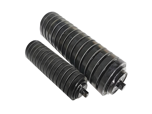
A conveyor roller machine does not always manufacture an entire roller in one operation. In a controlled roller-production process, specialized machines are often assigned to individual steps such as tube cutting, shaft milling, end preparation, bearing assembly, welding, and retaining-groove machining. Each machine creates a defined feature that the following production stage relies on.
Circlip grooving is one of these specialized shaft-processing operations. A groove machined at the correct position provides a controlled location for a retaining ring or related assembly component. When roller shafts are produced in batches, groove width, depth, axial position, and the relationship between the two shaft ends need to remain consistent from one workpiece to another.
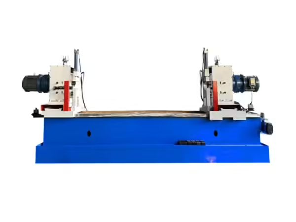
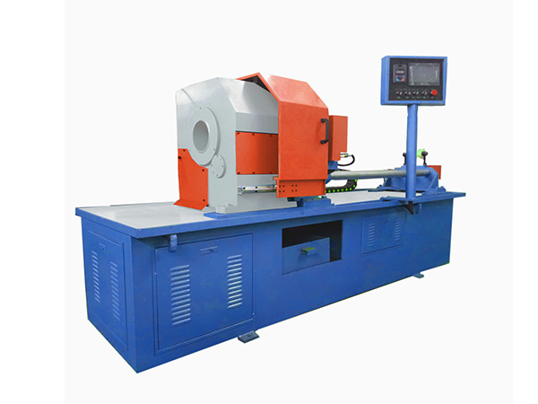
The Conveyor Roller Shaft Circlip Grooving Machine is designed specifically for this task. Instead of treating groove machining as a general workshop operation, the machine processes the corresponding groove positions at both ends of long conveyor roller shafts through one coordinated production cycle.
What Is a Conveyor Roller Machine for Circlip Grooving?
In this application, a conveyor roller machine is specialized equipment used to create retaining-ring grooves at the ends of belt conveyor roller shafts. It does not cut the roller tube or assemble the complete roller. Its purpose is to prepare one specific shaft feature required by certain roller designs.
The Conveyor Roller Shaft Circlip Grooving Machine is designed for shaft diameters from approximately Φ20 to Φ40 mm and shaft lengths from 280 to 2200 mm. Its double-end structure allows corresponding groove features at both sides of the shaft to be processed within the same machine setup.
This dedicated approach is important because the groove position needs to correspond with the final shaft drawing. If groove location varies between opposite ends or between production batches, later component installation can become less predictable even when the overall shaft length remains correct.
Why Circlip Grooves Are Machined Into Roller Shafts
A circlip is a retaining component designed to fit into a machined groove on a shaft or inside a bore. As explained in the general engineering definition of a circlip, the ring creates a retaining shoulder after installation and can restrict axial movement of the component it supports.
For conveyor roller shafts, the groove therefore needs to perform a functional mechanical role rather than simply create another visible machining feature. Its position relative to the shaft end and surrounding roller components needs to follow the actual assembly design.
Groove accuracy is especially important when several parts depend on the same axial reference. A groove located too far inward or outward can change the intended relationship between the retaining component and the neighboring assembly.
For this reason, circlip-groove machining should follow the technical drawing of the complete roller shaft.
Double-End Processing Reduces Datum Transfer
Traditional single-end processing requires the shaft to be machined on one side and then repositioned before the opposite end can be completed. Every repositioning operation introduces another opportunity for variation in workpiece location.
A double-end conveyor roller machine reduces this repeated datum transfer. The shaft is positioned within one machine setup while machining units at opposite sides process the corresponding groove features.
This arrangement is particularly useful for roller shafts because the workpiece itself is long and symmetrical. Corresponding end features normally need to maintain a controlled relationship with the same shaft centerline and overall length.
Reducing unnecessary repositioning does not eliminate the need for dimensional inspection, but it creates a more stable mechanical foundation for repetitive production.
TKC-2040 Processing Range
The TKC-2040 is designed around common conveyor roller shaft dimensions rather than general metalworking applications.
| Technical Item | TKC-2040 Reference |
|---|---|
| Roller shaft diameter | Φ20–40 mm |
| Roller shaft length | 280–2200 mm |
| Center height | 850 mm |
| Spindle speed | Frequency controlled |
| Hydraulic working pressure | 2.5–4.5 MPa |
| PLC | DELTA |
| Spindle motor | 4 kW |
| Machine weight | Approx. 2000 kg |
| Machine dimensions | 3700 × 1200 × 1100 mm |
These parameters define the machine envelope, but the actual shaft drawing still determines whether the equipment suits a particular roller specification. Groove geometry, shaft-end structure, material, and surrounding assembly features also need to be reviewed.
Shaft Diameter Influences the Machining Setup
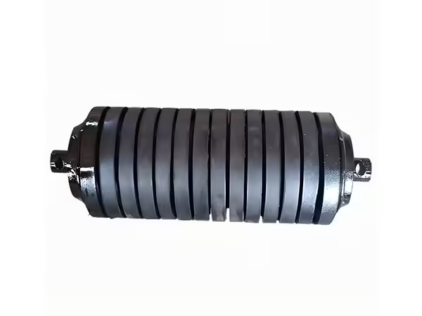
A Φ20 mm shaft and a Φ40 mm shaft present different cutting geometry even when they require a similar retaining groove. The relationship between the shaft centerline, cutting tool, and required groove depth changes with diameter.
The workpiece locating and clamping arrangement therefore needs to maintain a repeatable center position when the production specification changes.
If the shaft is not centered consistently, the groove can differ in depth or position even though the machine movement remains unchanged. First-piece measurement after a diameter change is therefore particularly useful.
The machine range of Φ20–40 mm provides flexibility for different roller shaft families, but each shaft size still requires the correct setup rather than one universal adjustment.
Shaft Length Requires Stable Support
Conveyor roller shafts are relatively long compared with their diameter. The TKC-2040 supports lengths from approximately 280 to 2200 mm, creating substantially different support conditions between the shortest and longest workpieces.
Long shafts need to remain aligned with the machine centerline so that both machining ends receive the workpiece in the intended position. Excessive sag or unsuitable supporting points can alter the relationship between the shaft and cutting units.
Machine setup should therefore consider both diameter and length. When a production batch changes from short shafts to long shafts, workpiece support deserves the same attention as cutter position.
Stable shaft support is one of the basic requirements for maintaining corresponding groove geometry at both ends.
Why Groove Position Matters
Groove position is normally defined from another shaft reference, such as the end face or another machined feature. This axial relationship determines where the retaining ring will sit after assembly.
A groove can have the correct width and depth while still being functionally incorrect if its axial location is wrong.
For batch manufacturing, the reference should therefore remain consistent across every shaft. Machine positioning, workpiece location, cutter condition, and shaft-end dimensions all contribute to the finished groove location.
This illustrates why groove machining needs to be connected with earlier shaft-preparation processes rather than treated as an isolated operation.
Groove Width and Depth Need to Work Together
A retaining groove is defined by several dimensions. Width determines the available space for the retaining component, while depth establishes how the ring engages with the shaft.
These dimensions should come directly from the finished part specification. Machining a deeper or wider groove without an engineering requirement does not improve the component and can change the remaining shaft geometry.
Cutting-tool dimensions, tool wear, radial position, and workpiece centering all influence the final groove.
Inspection should therefore confirm the physical workpiece rather than rely only on machine settings. The machine indicates the intended movement; measurement verifies the result.
Hydraulic Control Supports Repetitive Machining
The Conveyor Roller Shaft Circlip Grooving Machine uses a superposition-valve hydraulic system to control rapid forward and reverse movement of the spindle box and provide stepless processing adjustment.
This allows non-cutting travel and actual machining movement to be managed differently. Rapid approach reduces unnecessary auxiliary time, while the controlled machining stage maintains the required cutting relationship with the shaft.
The listed hydraulic working pressure is approximately 2.5–4.5 MPa. Stable pressure and suitable hydraulic condition are therefore part of maintaining a repeatable machine cycle.
Leaks, pressure instability, or valve problems can gradually alter machine movement even when PLC commands remain unchanged.
Frequency-Controlled Spindle Speed
The spindle uses frequency control rather than one fixed rotational condition. This provides flexibility when machining different roller shaft specifications.
The correct spindle condition depends on shaft material, groove dimensions, cutting-tool design, and the established machining procedure. Higher speed should not automatically be interpreted as better production.
Stable cutting requires a balanced relationship between spindle rotation, cutter engagement, feed movement, and workpiece support.
When changing shaft specifications, validated parameters can provide a stronger starting point than repeatedly rebuilding the setup through trial adjustment.
PLC Control Coordinates the Production Cycle
The TKC-2040 uses PLC-based program control together with non-contact switches for machine-position control.
In repetitive production, the PLC helps coordinate movement so the machining units follow the same general sequence from one shaft to the next. This reduces dependence on repeated manual operation during every cycle.
Automation is particularly useful for batch roller production because one validated sequence can be reproduced across many corresponding workpieces.
However, PLC control cannot compensate for incorrectly positioned raw material, worn tooling, unstable hydraulic pressure, or poor shaft support. Mechanical conditions still determine whether the programmed movements produce the intended feature.
How Circlip Grooving Fits Into Roller Shaft Processing
A conveyor roller shaft can require several independent features before it enters final assembly. Depending on the design, these may include flats, through-flats, grooves, chamfers, finished end faces, or center holes.
The wider conveyor roller manufacturing machinery range includes separate equipment for several of these operations. This allows each process to use machinery designed around the actual geometry it needs to create.
Circlip grooving should therefore be positioned within a defined shaft-processing sequence. The operations before it need to establish stable references, while the operations after it should preserve the groove location already produced.
A coordinated process reduces the possibility that one machining stage unintentionally changes a feature created earlier.
Circlip Grooving and Flat Milling Perform Different Functions
Flat milling creates mounting surfaces on the roller shaft, while circlip grooving creates a retaining feature. Although both operations remove material from the shaft, they serve different mechanical purposes.
The flat controls how the shaft interfaces with the conveyor mounting structure. The groove establishes an axial retaining position for the circlip or related component.
One feature should therefore not be used as a substitute for the other. If the finished shaft requires both, they need to be machined according to the same technical drawing so their relative locations remain controlled.
This is one reason dedicated shaft-processing machines are useful in conveyor roller manufacturing.
Circlip Grooving and Chamfering Are Also Different
Chamfering removes the sharp edge around a shaft end and creates a controlled transition between surfaces. A circlip groove, by contrast, forms a defined recessed feature along the shaft.
The two operations require different cutting geometry and perform different functions in the final component.
Where both are present, shaft-end length and other dimensional references need to remain consistent so that the chamfer and groove appear in the correct positions.
Separating these operations into clearly defined machining stages makes inspection more straightforward because each machine is responsible for a specific group of dimensions.
Incoming Shaft Quality Affects Groove Accuracy
Automatic machining is most repeatable when the incoming shafts already have stable dimensions.
Variations in diameter, straightness, length, or end condition can influence how the shaft sits within the machine. Even a precise conveyor roller machine cannot automatically remove all variation created by inconsistent raw workpieces.
Incoming shaft inspection should therefore confirm the dimensions that affect locating and cutting. The purpose is not to inspect every possible feature before machining but to identify conditions that influence the groove process.
Stable input material gives the automatic machine a predictable starting point.
Workpiece Clamping Must Preserve the Centerline
The shaft needs to remain in the same position throughout the machining cycle. If the clamping system allows movement, groove depth or position may change while cutting is taking place.
Contact surfaces should therefore remain clean and free from accumulated chips. Mechanical adjustment points should also be checked regularly, especially when the machine changes frequently between different shaft diameters.
Clamping force should stabilize the shaft without unnecessarily deforming or shifting it.
For a double-end machine, this requirement applies to the complete shaft because movement at one location can affect the relationship between both machining ends.
Tool Condition Influences Groove Geometry
The cutting tool creates the final groove width, depth, and surface condition. As the tool wears, cutting resistance can increase and the resulting feature can gradually change.
This deterioration may appear first as poorer surface quality, changing machining sound, dimensional drift, or increased vibration.
Tool inspection should therefore be connected with finished-workpiece measurements rather than based only on operating time.
When several consecutive shafts show a gradual dimensional change, tooling deserves attention before operators begin modifying machine reference settings.
First-Piece Inspection After Setup Changes
A first-piece inspection provides a practical checkpoint whenever shaft diameter, shaft length, cutting tool, groove specification, or machine setup changes.
Groove width, depth, position, and the relationship between left and right ends can be verified before the production batch continues.
This is especially important with automated equipment because the machine will reproduce the programmed cycle repeatedly. If the setup is incorrect, automation can reproduce that error across many shafts just as consistently as it reproduces a correct process.
Verifying the first workpiece creates a direct link between machine settings and the actual finished component.
Checking Left and Right Groove Consistency
A double-end conveyor roller machine provides a useful comparison because corresponding features are created at both ends of the same shaft.
If one side consistently produces a different groove, technicians can compare the two spindle units, cutting tools, hydraulic movements, workpiece supports, and positional adjustments.
A repeatable left-right difference often provides more diagnostic information than a random dimensional variation.
Inspection records should therefore distinguish which shaft end shows the change rather than recording only an overall pass or fail result.
This makes later troubleshooting more focused.
Diagnosing Groove Position Variation
When groove position varies along the shaft axis, the first checks should focus on workpiece locating and the dimensional reference used by the machine.
Incoming shaft length, end-face consistency, locating stops, clamping position, and machine movement should all be reviewed before cutter geometry is changed.
If the position changes gradually through a long batch, fixture wear or movement also deserves attention.
Changing the programmed groove location without identifying the mechanical cause can temporarily hide the problem while creating another dimensional error elsewhere.
Diagnosing Groove-Depth Variation
Groove-depth variation often points toward the relationship between shaft centerline and cutting-tool position.
Shaft diameter variation, incorrect centering, tool wear, spindle movement, clamping, and machine adjustment can all affect the final depth.
Both ends should be compared because a problem appearing only on one side can narrow the inspection to one machining unit.
If both ends change in the same direction, incoming shaft dimensions or a shared machine condition may deserve closer attention.
Diagnosing Poor Groove Surface Quality
Surface quality can deteriorate even when groove dimensions remain within the intended range.
Possible causes include cutting-tool wear, unsuitable spindle conditions, vibration, unstable clamping, material variation, or chip accumulation around the machining zone.
The workpiece should first be checked for secure positioning before cutting parameters are changed.
A structured troubleshooting sequence helps separate a tool problem from a machine or material problem and reduces unnecessary adjustment of several variables at the same time.
Maintenance of the Hydraulic System
The hydraulic system controls important spindle-box movements, so pressure stability and fluid-system condition influence the production cycle.
Routine checks should include hoses, fittings, valves, seals, hydraulic fluid, and signs of leakage. Changes in movement speed or machine sound can provide early indications that the system requires attention.
Hydraulic maintenance should be performed before unstable movement begins affecting groove dimensions.
In repetitive shaft production, preventive attention is particularly valuable because one developing mechanical issue can otherwise influence many components in the same batch.
Maintenance of Spindles and Cutting Units
Both spindle units should be inspected because they produce corresponding features on opposite ends of the same workpiece.
Cutter mounting, spindle condition, fastening, abnormal vibration, and cutting-tool wear should be compared between the two sides.
If one side begins producing different results, the matching side provides an immediate internal reference for troubleshooting.
This is one of the useful characteristics of a double-end machine: the completed shaft itself provides two corresponding features that can be evaluated against one another.
Chip Control Around Locating Surfaces
Machining grooves creates metal chips that can accumulate around the cutting area and machine fixtures.
If chips reach locating or clamping surfaces, they can alter the position of the next shaft even when the machine setup has not been intentionally changed.
Regular cleaning therefore contributes directly to dimensional repeatability.
Automatic production should not be interpreted as maintenance-free production. The more consistently the machine repeats its cycle, the more important it becomes to keep the physical reference surfaces in a stable condition.
Why Batch Production Benefits From Dedicated Equipment
General-purpose machinery can perform many different operations, but every workpiece may require additional locating, adjustment, or manual handling.
A specialized conveyor roller machine is designed around one repeated workpiece family and one defined operation. In the case of the TKC-2040, that operation is double-end circlip-groove machining on roller shafts.
This specialization allows workpiece support, center height, hydraulic movement, spindle arrangement, and PLC sequencing to be organized around long cylindrical shafts.
The advantage is not that the machine can perform every operation. It is that one required operation can be reproduced within a controlled production process.
Relationship With Final Roller Assembly
The machined shaft eventually becomes part of the roller assembly together with the roller tube, bearings, bearing housings, seals, and other design-specific components.
Groove position needs to remain compatible with these surrounding parts. A correctly machined groove located from an incorrect reference can still create problems later during assembly.
For this reason, inspection requirements should originate from the final shaft drawing rather than only from machine capability.
The conveyor roller machine creates the feature, but the completed roller determines whether that feature performs its intended mechanical function.
A Practical Process-Control Checklist
Stable circlip-groove machining depends on several related factors.
| Control Area | What to Verify |
|---|---|
| Incoming shaft | Diameter, length, straightness |
| Workpiece position | Centerline and locating reference |
| Clamping | Stability during machining |
| Groove geometry | Width, depth, axial location |
| Left/right relationship | Corresponding end consistency |
| Cutting tool | Wear and mounting |
| Spindle | Stable rotation |
| Hydraulic system | Pressure and movement |
| PLC cycle | Correct sequence |
| Inspection | First piece and periodic checks |
These checks create a stronger production method than monitoring machine speed alone.
Common Mistake: Treating Circlip Grooving as General Milling
A circlip-grooving machine removes material from a shaft, but the process should not be confused with ordinary flat milling.
The groove has a specific retaining function and requires defined width, depth, and axial position. Flat milling produces a different geometry for another mechanical purpose.
Using the correct process description helps manufacturers select equipment and inspection methods that correspond with the actual shaft feature.
The finished drawing should always remain the main reference.
Common Mistake: Checking Only Groove Width
Groove width is easy to measure, but it provides only one part of the finished geometry.
Depth and axial position also influence how the retaining component fits the shaft. A groove can have correct width while still being too shallow, too deep, or incorrectly located.
Inspection should therefore evaluate the functional geometry rather than one isolated dimension.
For double-end shafts, the relationship between opposite grooves should also be checked.
Common Mistake: Ignoring Earlier Shaft Operations
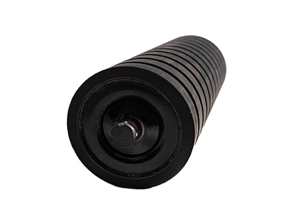
If groove position repeatedly changes, the source may exist before the shaft reaches the circlip-grooving machine.
Inconsistent end facing, shaft length, flat machining, or other upstream preparation can change the reference condition used by later equipment.
Troubleshooting should therefore follow the complete shaft-processing sequence rather than assume the last machine is always responsible.
A stable conveyor roller manufacturing process depends on predictable workpiece transfer between each stage.
Conclusion
A conveyor roller machine for circlip grooving performs a specialized but important function within roller shaft manufacturing. Instead of attempting to manufacture the entire roller, the machine creates the retaining grooves required at corresponding shaft-end positions.
The TKC-2040 is designed for shafts with diameters of approximately Φ20–40 mm and lengths from 280 to 2200 mm. Its hydraulic spindle-box movement, frequency-controlled spindle, PLC-based sequencing, and double-end structure support repetitive groove machining for batch roller production.
Reliable results still depend on stable incoming shafts, correct locating, secure clamping, suitable cutting tools, hydraulic condition, first-piece verification, and periodic dimensional inspection. Groove width alone is not enough; depth, axial position, and left-right consistency also need to match the finished shaft drawing.
When these factors are controlled together, circlip grooving becomes a predictable shaft-processing stage that integrates naturally with flat milling, chamfering, bearing assembly, and other conveyor roller manufacturing operations.
FAQ
What is a conveyor roller machine used for in circlip grooving?
In this application, a conveyor roller machine is specialized equipment used to machine retaining-ring grooves at both ends of a conveyor roller shaft. The groove provides a defined position for a circlip or related retaining component and needs to match the shaft drawing in width, depth, and axial location.
What shaft range can the TKC-2040 process?
The TKC-2040 is designed for conveyor roller shafts with diameters of approximately Φ20–40 mm and lengths from 280 to 2200 mm. It uses a double-end structure so corresponding groove positions at both ends can be processed within one machine setup.
Why is double-end circlip grooving useful?
Double-end processing reduces repeated workpiece repositioning and allows corresponding grooves to remain referenced to the same shaft setup. This is useful in batch roller production where the left and right groove locations need to maintain a consistent relationship with overall shaft length and other machined features.
What should be inspected after circlip-groove machining?
Inspection should verify groove width, groove depth, axial location, surface condition, and the relationship between corresponding grooves at both shaft ends. The incoming shaft diameter and length should also be confirmed because workpiece variation can affect the finished groove even when machine settings remain unchanged.
How does circlip grooving fit into conveyor roller manufacturing?
Circlip grooving is one stage within roller shaft processing. Depending on the finished design, the shaft may also require flat milling, through-flat milling, end facing, chamfering, or center-hole machining before assembly. Each process should use the same technical drawing so the individual shaft features remain dimensionally compatible.
 English
 French
 Spanish