

Table of Contents
Introduction
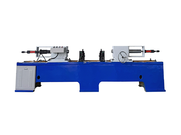
Automatic welding in conveyor roller production is not simply a matter of replacing manual torch movement with a powered mechanism. The roller is a long cylindrical workpiece with corresponding joints at opposite ends, so successful automation depends on how accurately the machine centers, clamps, rotates, positions, and welds the complete assembly. Upstream tube machining and bearing assembly also influence the geometry presented to the welding station.
For manufacturers producing conveyor rollers in repeated batches, these relationships make machine design especially important. A suitable system should maintain a predictable workpiece centerline, allow both ends to be processed within one coordinated setup, and provide stable control over rotation, welding position, shielding conditions, and production sequencing.
Evaluating an automatic welding machine manufacturer should therefore focus on the complete manufacturing process rather than one electrical specification. The following seven checks explain the technical factors that matter when selecting automatic double-end welding equipment for conveyor roller production.
Check 1: Is the Machine Designed for Conveyor Roller Geometry?
The first consideration is whether the welding equipment is actually designed around the workpiece being manufactured. Conveyor rollers have a long cylindrical structure, corresponding joints at both ends, and dimensional requirements that differ from flat plates or irregular fabricated components. A general welding platform may be able to create a weld, but that does not mean its workpiece supports, clamping system, rotational mechanism, and torch positions are optimized for roller production.
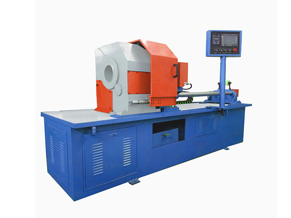
The existing double-end automatic roller welding machine is designed around cylindrical workpieces and provides automatic centering, pneumatic clamping, controlled rotation, and simultaneous welding at both ends. This structure allows the machine to establish one common mechanical reference before the welding cycle begins.
For conveyor roller manufacturers, this dedicated workpiece approach is important because the objective is not merely to complete a joint. The machine must preserve the relationship between the roller tube, shaft, bearing-related components, and corresponding welded areas throughout repetitive production.
Check 2: Can Both Roller Ends Be Welded in One Setup?
A conveyor roller normally contains similar assembly features at both ends. If each side is welded independently, the workpiece must be repositioned or reversed, creating an additional setup between corresponding operations. Every extra setup introduces another opportunity for variation in centering, clamping, torch position, and joint location.
A double-end automatic welding structure processes both sides while the roller remains within the same machine reference. Once the workpiece is centered and secured, the two welding positions can operate during the same production cycle. This reduces unnecessary handling and helps maintain a more consistent relationship between opposite joints.
The benefit becomes particularly clear in batch production. Rather than repeatedly recreating two separate setups for every roller, the machine establishes one coordinated process that can be reproduced across multiple workpieces of the same specification.
Why Simultaneous Welding Requires Accurate Upstream Assembly
Double-end welding works most effectively when the components entering the machine have already been positioned consistently. If a bearing housing or other welded component sits at a different location from one roller to another, the welding joint will also appear at a different position relative to the torch.
This means automatic welding cannot compensate reliably for dimensional variation created earlier in production. Tube cutting, tube-end machining, shaft preparation, bearing setting, and component assembly all contribute to the geometry presented to the welding machine.
A technically capable automatic welding machine manufacturer should therefore understand the upstream roller manufacturing process. Welding equipment performs best when it receives components that have already been machined and assembled around stable dimensional references.
Check 3: How Does Automatic Centering Work?
Centering determines the relationship between the cylindrical workpiece and the machine’s rotational axis. If the roller is noticeably off-center, the distance between the welding torch and joint can change as the workpiece rotates, even when the welding parameters remain unchanged.
Automatic centering helps establish a repeatable starting condition before clamping and welding begin. The roller is positioned according to the machine centerline, after which the clamping system secures that relationship for the remainder of the cycle.
This reduces dependence on repeated manual adjustment and is especially useful when the same roller specification is manufactured continuously. The machine does not need to rediscover the workpiece axis through operator judgment before every weld.
Centering accuracy should still be supported by correctly manufactured components. A bent shaft, deformed tube, or poorly assembled roller cannot be corrected simply by an automatic centering mechanism.
Check 4: Is the Clamping System Suitable for Cylindrical Workpieces?
After centering, the roller needs to remain stable while rotation and welding take place. The clamping mechanism must secure the workpiece without interfering with its intended movement or shifting the established centerline.
The current double-end welding equipment uses pneumatic clamping. This provides a repeatable method of holding the roller before the welding cycle begins and releasing it after both ends have been completed.
Clamping surfaces, actuators, air supply, and adjustment mechanisms should remain in suitable condition because gradual wear or contamination can change how the roller is positioned. Even a small change at the clamping stage can influence torch-to-joint distance once the workpiece begins rotating.
For this reason, clamping should be evaluated as part of welding accuracy rather than as a separate loading convenience.
Check 5: Can the Rotation System Maintain Stable Circumferential Welding?
Circumferential roller welding depends on controlled relative movement between the joint and welding torch. Instead of moving the torch around the complete circumference, the machine can rotate the cylindrical workpiece while the welding heads remain at defined positions.
The TH-220×2200 configuration provides adjustable welding rotation from approximately 0 to 10 rpm. The appropriate operating condition depends on roller diameter, joint geometry, welding current, wire feed, shielding conditions, and the established welding procedure.
Stable rotation is important because irregular workpiece speed changes the travel relationship between the arc and the joint. Even if current and wire settings remain unchanged, inconsistent rotation can alter the amount of welding energy applied over a given section of the circumference.
An automatic welding machine manufacturer should therefore treat the rotational system as a core part of welding control rather than simply as a workpiece positioning device.
Matching Rotation to Roller Diameter
A smaller roller and a larger roller have different circumferences, so rotational speed needs to be considered together with the required welding travel condition. The objective is to maintain a suitable relationship between workpiece movement and the welding process as the joint passes beneath the torch.
The TH-220×2200 supports workpiece diameters from approximately Φ76 to Φ219 mm. This range means the same machine can process several common conveyor roller sizes, but production settings may need adjustment when diameter changes significantly.
A validated setup for each frequently produced roller specification can help make these transitions more repeatable. The first completed roller after a change should then be inspected before the remaining batch proceeds.
Check 6: Does the Welding System Support the Required Process?
The equipment uses gas-shielded arc welding methods appropriate for steel cylindrical workpieces. Depending on the established process, shielding-gas combinations and flux-cored wire CO₂ welding can be used.
In gas metal arc welding, a continuously fed consumable electrode forms the weld while shielding gas protects the arc and molten metal from atmospheric contamination. Automatic machinery can coordinate this welding process with controlled workpiece rotation, clamping, and torch position.
The TH-220×2200 lists a welding-current range of approximately 60–350 A and shielding-gas flow of approximately 10–25 L/min. These values describe available machine capability rather than universal settings. The actual operating parameters should be established according to roller material, joint design, wire, shielding system, and required weld geometry.
A manufacturer should therefore provide equipment flexibility while recognizing that the welding procedure must still be matched to the actual workpiece.
Shielding Stability Matters During Automatic Welding
Shielding gas needs to reach the welding zone consistently throughout the complete rotation of the roller. Restrictions, leaks, unstable regulation, or incorrect torch position can change the protection surrounding the molten weld even when other machine parameters remain unchanged.
Gas lines, connections, regulators, and delivery components should therefore be included in routine machine inspection. Operators should also monitor whether changes in weld appearance correspond with changes in gas delivery or surrounding airflow.
Automatic welding improves repeatability only when all process inputs remain controlled. Stable rotation and PLC sequencing cannot compensate for an inconsistent shielding environment.
Check 7: Does PLC Control Coordinate the Whole Welding Cycle?
An automatic welding cycle contains several dependent steps. The roller needs to be loaded, centered, clamped, positioned, rotated, welded, stopped, released, and removed in the correct sequence. If one action happens at the wrong time, the process can become unstable even if the welding power source itself performs correctly.
PLC control coordinates these machine functions according to a defined sequence. Compared with relying on separate manual operations, this allows repeated rollers to follow the same basic production logic throughout a batch.
The broader roller manufacturing machinery range also uses dedicated equipment for tube cutting, shaft processing, bearing setting, and related stages. Coordinating these operations around repeatable machine cycles creates a more stable manufacturing route from raw material to completed roller.
PLC control should therefore be evaluated as part of process integration rather than only as an electrical feature.
Technical Parameters Should Match the Real Roller Range
Machine selection should start with the roller families that will actually be produced. Diameter, length, joint position, material, welded component geometry, and expected production sequence all influence whether the machine working range is suitable.
| Technical Item | TH-220×2200 Reference | Manufacturing Relevance |
|---|---|---|
| Workpiece diameter | Φ76–219 mm | Covers multiple roller diameters |
| Workpiece length | 200–2200 mm | Supports short and long rollers |
| Machine center height | 850 mm | Establishes workpiece reference |
| Welding current | 60–350 A | Supports process adjustment |
| Shielding-gas flow | 10–25 L/min | Supports gas-shielded welding |
| Rotation speed | 0–10 rpm | Allows circumferential control |
| Rated capacity | 50 KVA | Supports welding system |
| Clamping | Pneumatic | Secures cylindrical workpiece |
| Control | PLC-based | Coordinates automatic cycle |
These parameters should be reviewed together because no single value determines whether the machine fits a roller production program.
Why Workpiece Length Matters
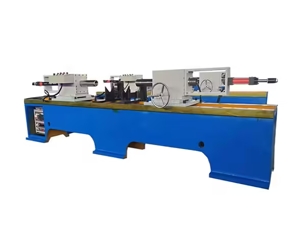
Long rollers need stable support throughout welding. If the workpiece sags or shifts between supporting points, the joint position can move relative to the welding heads even when the machine centerline is correct.
The TH-220×2200 accommodates workpieces from approximately 200 to 2200 mm, which means support conditions need to work across a relatively broad range of roller lengths.
When production changes from a short roller to a much longer component, support position and welding-head location should be checked as part of the setup. The objective is to keep the roller axis stable throughout rotation rather than simply fit the workpiece between the machine ends.
Why Welding Current Is Not the Only Quality Variable
Welding current is important, but it represents only one part of the overall process. Wire feed, voltage, shielding gas, rotation speed, torch position, joint geometry, workpiece cleanliness, and component alignment all contribute to the finished weld.
Increasing current does not solve a joint-position problem caused by poor assembly, nor does changing rotation speed correct a contaminated shielding system. Troubleshooting should therefore follow the actual production sequence rather than adjust one electrical parameter whenever weld appearance changes.
An automatic welding machine manufacturer with strong process understanding should be able to connect machine movement with welding conditions and workpiece geometry.
Integration With Bearing Setting
In many roller manufacturing routes, bearing-related assembly occurs before final welding. The pressing stage determines where components sit relative to the roller tube and shaft, which means its dimensional consistency directly affects the welding joint.
If opposite components are positioned differently during bearing setting, the double-end welding machine receives a workpiece whose left and right joints no longer match the validated setup. Welding equipment may continue following the correct program while the workpiece itself has changed.
This connection explains why automated production should be considered across several stages. Stable bearing assembly creates more predictable welding conditions, while stable welding preserves the geometry established upstream.
Integration With Tube-End Machining
The roller tube also passes through machining stages before welding. Cut length, end-face geometry, bearing-seat preparation, and component position all influence the final joint location.
Consistent double-end tube machining helps ensure that corresponding structures at both ends maintain a predictable relationship. The welding machine can then position its two heads according to a stable workpiece geometry rather than compensate for differences created earlier.
For batch production, this process connection becomes one of the strongest reasons to use dedicated roller manufacturing machinery. Each stage creates the reference condition needed by the next.
First-Piece Verification After a Setup Change
When roller diameter, length, joint position, wire, shielding condition, or another significant process parameter changes, the first completed workpiece should receive additional inspection.
The operator can verify joint location, visible weld consistency, correspondence between both ends, rotational behavior, and any dimensional requirements relevant to the final roller. This confirms whether the new setup produces the intended result before the same conditions are repeated across a larger batch.
First-piece verification is especially useful in automatic production because automation can reproduce both correct and incorrect settings with equal consistency. Validating the setup before continuous operation prevents one mistake from being multiplied.
Checking Left and Right Weld Consistency
Double-end equipment provides a useful diagnostic advantage because two corresponding welds are produced on the same workpiece within one machine cycle. Their condition can therefore be compared directly.
If one side repeatedly differs from the other, technicians should examine torch position, wire delivery, shielding gas, clamping, workpiece alignment, welding-head adjustment, and component geometry on the affected side.
A recurring difference is more informative than an isolated variation. It can indicate that one side of the machine or one upstream component position requires attention.
This left-to-right comparison should become part of routine production monitoring.
Diagnosing Irregular Circumferential Welds
When weld appearance changes around the circumference, the rotational system should be included in troubleshooting. Irregular speed, workpiece runout, off-center positioning, unstable clamping, or changing torch distance can all alter conditions as the roller turns.
Technicians should first determine whether the variation occurs at the same rotational position on repeated rollers. A consistent location can point toward workpiece geometry or machine alignment, while random variation may suggest another process input.
This structured approach reduces unnecessary parameter changes and makes it easier to separate welding-process problems from mechanical positioning problems.
Diagnosing Workpiece Runout During Welding
Visible runout means the outer surface or welded joint does not follow a stable circular path around the machine axis. The cause may originate from the roller itself, the upstream assembly process, centering, clamping, or support conditions.
The welding machine should not automatically be assumed responsible. The roller should first be checked for tube straightness, component alignment, and bearing-related assembly geometry before machine settings are changed.
If several correctly manufactured workpieces show the same runout pattern only after loading into the machine, the centering, supports, or clamping system may require closer inspection.
Maintenance of the Rotation System
The drive and rotational components need to maintain predictable movement throughout repeated welding cycles. Mechanical wear, looseness, contamination, or irregular drive behavior can gradually influence circumferential consistency.
Routine inspection should consider bearings, drive components, support surfaces, fastening, and any mechanism involved in workpiece rotation. Changes in sound or vibration should be investigated before they produce a visible change in weld quality.
Preventive maintenance is particularly useful in automatic welding because small mechanical changes can be repeated across many workpieces before they become severe enough to stop production.
Maintenance of Pneumatic Clamping
Pneumatic clamping needs reliable pressure and stable mechanical contact with the workpiece. Air leaks, worn clamping surfaces, loose adjustment points, or contamination can alter the way the roller is held.
Clamps should therefore be inspected together with air lines, valves, actuators, and workpiece-contact surfaces. Their movement should remain smooth and predictable across repeated production cycles.
Because clamping establishes the physical position of the roller before welding, maintenance in this area directly supports centering and torch alignment.
Welding-Head and Wire-Feeding Maintenance
The welding heads need to maintain their intended position relative to the roller joint. Mechanical looseness or incorrect adjustment can gradually change this relationship even when the control program remains unchanged.
Wire feeding also needs to remain stable because irregular delivery changes the welding process itself. Feed components and consumables should therefore be checked according to the equipment and established welding procedure.
Maintenance should combine machine inspection with observation of finished welds. Changes in appearance can provide early feedback about mechanical or consumable conditions that are beginning to drift.
Why Machine Rigidity Matters
A double-end welding machine needs to maintain the relationship between the workpiece supports, clamping system, rotational axis, and welding heads while the roller turns. Structural movement or loose machine components can change this geometry during operation.
Machine rigidity is therefore important even though welding removes less material than a cutting or milling process. The goal is to keep the relative position of the workpiece and torches stable throughout the complete circumference.
Long workpieces make this relationship particularly important because small positional changes can become more visible across the full roller length.
Batch Production Requires Repeatable Changeovers
Roller manufacturers often produce several diameters and lengths using the same equipment. Every changeover can affect supports, head positions, clamping adjustment, rotation settings, and welding parameters.
Documented setup information helps operators return to validated conditions when a frequently produced roller specification appears again. This can include mechanical positions as well as established welding parameters.
Repeatable changeovers reduce dependence on trial adjustment and allow first-piece inspection to focus on confirming the setup rather than rebuilding the process from the beginning.
Evaluate the Manufacturer by Process Knowledge
A strong automatic welding machine manufacturer should understand the difference between simply supplying a welding power source and designing a machine around a repetitive industrial workpiece.
For conveyor roller production, the manufacturer should be able to discuss centering, simultaneous double-end welding, pneumatic clamping, workpiece rotation, PLC sequencing, roller dimensions, shielding conditions, and integration with bearing-setting and tube-machining processes.
This process knowledge matters because machine performance depends on how these systems interact. The best technical solution is one that fits the actual roller production route rather than adding automation without considering upstream and downstream manufacturing.
Avoid Expanding the Machine Beyond Its Real Application

Automatic welding is a broad industrial term, but equipment should always be evaluated according to its actual design. The machine discussed here is a double-end gas-shielded welding system for cylindrical workpieces such as conveyor rollers and related components.
It should not be treated as a laser welding system, robotic multi-axis cell, or unrelated sheet-metal welding platform. Those processes use different machine structures and solve different manufacturing tasks.
Keeping the application precise is important for both equipment selection and production planning. Conveyor roller manufacturers need machinery designed around the geometry they actually process rather than a broad welding label.
Conclusion
Evaluating an automatic welding machine manufacturer for conveyor roller production requires attention to far more than welding current. The machine needs to center long cylindrical workpieces, secure them reliably, rotate them under controlled conditions, position two welding heads accurately, and coordinate the complete cycle through a stable control system.
Double-end simultaneous welding is particularly suitable for conveyor rollers because corresponding joints can be processed while the workpiece remains within one machine setup. Automatic centering, pneumatic clamping, PLC sequencing, adjustable rotation, and gas-shielded welding then create a repeatable framework for batch manufacturing.
The strongest production results come when welding is integrated with the processes before it. Consistent tube machining and bearing assembly provide predictable joints, while first-piece verification and routine maintenance help preserve that condition during longer production runs.
For this reason, an automatic welding machine should be evaluated as part of the complete conveyor roller manufacturing process rather than as an isolated welding station.
FAQ
What should be checked when evaluating an automatic welding machine manufacturer?
Evaluation should include workpiece range, automatic centering, double-end welding capability, pneumatic clamping, rotational control, welding-process compatibility, PLC sequencing, machine rigidity, maintenance accessibility, and integration with upstream roller machining and assembly. These factors determine whether the equipment fits repetitive cylindrical workpiece production.
Why is double-end automatic welding useful for conveyor rollers?
Conveyor rollers normally have corresponding welded joints at opposite ends. Double-end equipment allows both sides to be processed while the roller remains within one machine setup, reducing repeated repositioning and helping maintain a more consistent mechanical relationship between the two weld locations during batch production.
What workpiece range does the TH-220×2200 welding machine support?
The TH-220×2200 configuration supports cylindrical workpieces with diameters of approximately Φ76–219 mm and lengths from 200 to 2200 mm. Its listed welding-current range is 60–350 A, shielding-gas flow is 10–25 L/min, and workpiece rotation can be adjusted within approximately 0–10 rpm.
Why is automatic centering important in roller welding?
Automatic centering establishes the roller relative to the machine’s rotational axis before clamping and welding begin. This helps keep the circumferential joint in a more predictable relationship with the welding heads as the roller turns, reducing dependence on repeated manual alignment between successive workpieces.
How does upstream roller assembly affect automatic welding?
Tube machining and bearing-related assembly determine where the welded components sit relative to the roller axis. If those dimensions vary, the welding joint also moves even when the welding machine keeps the same settings. Stable upstream processing therefore provides the predictable workpiece geometry required for consistent automatic welding.
 English
 French
 Spanish