

Table of Contents
Introduction
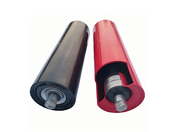
Conveyor idler rollers form the rotating support structure beneath industrial belt conveyors, but selecting the correct roller involves far more than matching an outside diameter. Belt width, roller length, shaft geometry, bearing size, sealing structure, idler arrangement, operating environment, and engineering standard all influence whether the roller can fit the conveyor correctly and maintain stable operation.
This becomes particularly important in mining, quarrying, cement, steel, power generation, and other bulk-material handling systems, where large numbers of idlers may operate continuously under dust, moisture, vibration, abrasive contamination, and repeated mechanical loading. When the same dimensional or assembly difference is repeated across many roller positions, a small specification problem can become a conveyor-wide issue.
For this reason, conveyor idler rollers should be specified as engineered components within a complete belt-support system. This guide focuses on dimensional compatibility, standard references, internal structure, and the relationship between the roller and conveyor frame rather than treating every idler as a universal replacement part.
What Are Conveyor Idler Rollers?
Conveyor idler rollers are non-driven cylindrical components used to support and guide a moving conveyor belt. The roller shell rotates around bearings installed on a central shaft, while the shaft transfers load into the supporting bracket or conveyor frame.
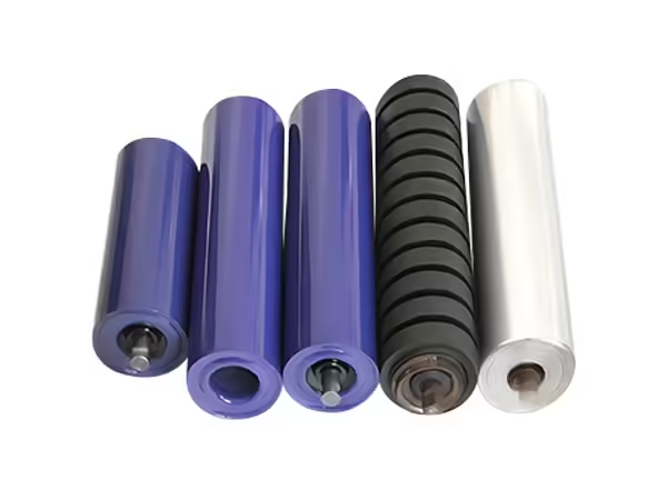
The available conveyor idler roller configurations include standard conveyor rollers, buffer rollers, parallel rollers, and conveyor roller sets. These products are intended for different conveyor positions and should therefore be selected according to their mechanical function rather than only by external dimensions.
Inside the roller, the tube, shaft, bearings, bearing housings, and seals need to maintain a controlled relationship around the intended rotational axis. Outside the roller, shaft-end geometry and bracket dimensions determine whether the component fits the surrounding conveyor structure correctly.
Why Engineering Standards Matter
Industrial conveyor projects may use different dimensional and engineering frameworks depending on the system design, region, installed equipment, and project specification. The current roller range supports CEMA, ISO, GB, JIS, and DIN references, which allows the roller structure to be matched with different engineering requirements.
A standard provides a common technical language, but it does not replace the actual conveyor drawing. Belt width, roller spacing, shaft ends, bearing selection, sealing environment, and supporting frame still need to be checked because two conveyors using similar standards can operate under very different conditions.
The practical value of a standard is therefore consistency. It helps engineers communicate dimensional expectations, but the final roller specification still needs to reflect the physical conveyor in which the component will operate.
Belt Width Is the Starting Dimensional Reference
Belt width strongly influences the overall idler arrangement because the supporting rollers need to maintain contact across the required carrying or return section. The current product range covers idler belt widths from approximately 500 mm to 2800 mm.
However, belt width alone does not determine individual roller length. A single flat return roller can span a large portion of the belt, while a troughing idler divides support among several rollers installed at different angles. The complete idler geometry therefore needs to be understood before individual roller dimensions are finalized.
When replacing rollers in an existing system, technicians should measure the actual mounting structure instead of assuming that belt width automatically corresponds with one standard roller length.
Roller Diameter Must Match the Complete Structure
The available conveyor roller configurations cover multiple diameters, lengths, bearing sizes, sealing structures, materials, and idler arrangements. Roller diameter therefore needs to be considered together with shaft geometry, bearing selection, belt width, installation position, and the surrounding conveyor frame rather than treated as an independent specification.
Roller Length Depends on Idler Geometry
The current roller range extends from approximately 160 mm to 2800 mm, but length should always be interpreted together with idler type and mounting structure.
In a three-roller troughing set, the center and side rollers divide the total belt-support width. Their individual lengths and installation angles establish the carrying profile. A flat or return arrangement uses a different geometry, which means the same belt width can require substantially different roller lengths depending on the idler design.
This is why technical drawings should distinguish roller body length, overall shaft length, mounting width, and actual belt-contact area instead of describing all of these dimensions with one general “roller length” value.
Shaft Dimensions Determine Installation Compatibility
The shaft provides the fixed central support around which the roller shell rotates. Its diameter influences bearing selection, while its total length and end geometry determine how the roller connects with the conveyor frame.
Different idler structures can require flats, grooves, or other shaft-end features. These dimensions should be checked carefully during replacement because a roller with the correct shell diameter and tube length can still be incompatible if its shaft does not fit the existing bracket.
Manufacturing consistency is equally important. Corresponding shaft features at both ends should maintain the required relationship so that every roller in the same batch fits the supporting structure in a predictable way.
Bearing Size Must Match Shaft and Housing Geometry
Bearings create the rotational interface between the roller shell and central shaft. The available roller configurations support several deep-groove ball bearing sizes, including 6204, 6205, 6206, 6304, 6305, 6306, 6307, 6308, 6310, 6312, and 6406 arrangements.
These bearing options should not be treated as interchangeable. Bearing dimensions affect shaft diameter, bearing housing design, and the sealing structure surrounding the bearing area.
A larger bearing designation does not automatically make a conveyor idler roller more suitable. The bearing should match the mechanical load, shaft structure, roller diameter, housing geometry, and intended operating environment as one integrated system.
Bearing Housings Keep the Rotating Structure Aligned
The bearing housing positions the bearing within the roller tube and helps establish the relationship between the rotating shell and shaft. If housings at opposite ends do not remain aligned around the same intended axis, the completed roller can develop rotational variation even when individual component dimensions appear acceptable.
Housing geometry therefore needs to correspond with both the bearing and roller shell. During manufacturing, its position should remain controlled so that later assembly does not introduce unnecessary misalignment.
This internal geometry is one reason why conveyor idler rollers cannot be evaluated from external dimensions alone. Several of the most important dimensional relationships are hidden inside the completed component.
Sealing Structure Should Match the Environment
The roller end is exposed to the operating environment while the bearing needs to remain protected inside the assembly. Dust, water, fine particles, and other contaminants can gradually approach the bearing area if the sealing structure is unsuitable or damaged.
The current product configurations support TK, TKII, DTII, TD75, and TKIII sealing arrangements. Each structure needs to correspond with the shaft, bearing housing, and bearing design rather than being selected independently.
For dusty mining or cement applications, sealing may become one of the most important internal design considerations. In cleaner environments, the same level of protection may not be required, which demonstrates why operating conditions need to be included in the technical specification.
Idler Type Changes the Required Geometry
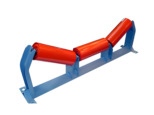
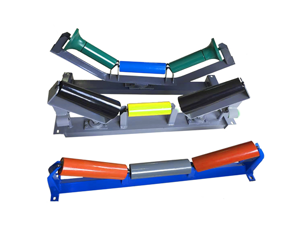
The existing product range supports trough, flat, V-return, training, self-aligning, garland, and offset conveyor idler roller configurations. These terms describe different support functions and arrangements rather than cosmetic variations of the same product.
A troughing configuration shapes the loaded belt for bulk-material carrying, while flat and return arrangements support different sections of the belt path. Training and self-aligning structures are associated with belt guidance, and garland or offset arrangements use different mounting geometry.
For this reason, conveyor idler rollers should always be specified together with their intended position. Knowing the roller diameter without knowing the idler function provides only part of the information required for correct engineering selection.
Troughing Idlers Require Set-Level Compatibility
A troughing idler normally contains several rollers working together to create the desired belt profile. The bracket determines the position and angle of each roller, while individual shaft ends connect the rollers with the supporting structure.
Because several rollers share the load, differences in mounting height or angle can change how the belt contacts the complete set. One roller positioned differently can carry an unintended proportion of the load even when its own dimensions are technically correct.
Troughing idlers should therefore be evaluated at both component and assembly level. Individual roller specifications and complete bracket geometry need to remain compatible.
Return Idlers Have Different Operating Conditions
Return rollers support the belt after conveyed material has been discharged. The primary bulk load is no longer present, but contamination, residual material, alignment, and belt sag can still influence the roller.
Material attached to the returning belt may accumulate on the roller surface or around its ends, which means bearing protection remains relevant even when load conditions differ from the carrying side.
Return-side roller selection should therefore consider the actual environment and support geometry rather than simply using the same specification found on the loaded side.
Buffer Rollers Are Intended for Impact Areas
Loading zones expose the conveyor to dynamic forces when material falls onto the belt. Buffer rollers are designed specifically for this type of position and should not be confused with normal carrying rollers installed farther along the conveyor.
The existing product category includes Buffer Roller as a real product intended to reduce the impact of material on the belt and supporting rollers.
The correct configuration depends on loading height, material characteristics, conveyor geometry, belt construction, and surrounding idler structure. This reinforces the principle that idler position needs to be defined before individual roller specifications are finalized.
Material Selection Should Follow the Application
The current Conveyor Rollers product information includes carbon steel, stainless steel, rubber, nylon, PVC, HDPE, and UHMWPE as available roller pipe materials, while shaft options include carbon steel and stainless steel.
These materials have different mechanical, corrosion, mass, and environmental characteristics. Their suitability therefore depends on the conveyor rather than one material being universally superior.
A heavy industrial application may emphasize structural rigidity, while another environment may place more importance on corrosion behavior or specific material characteristics. Material selection should always be reviewed together with bearings, seals, dimensions, and operating conditions.
Surface Treatment and Internal Sealing Solve Different Problems
Steel conveyor idler rollers can use finishes such as powder coating, conventional painting, or galvanized treatment according to the external environment.
These treatments protect exposed surfaces, but they should not be confused with internal bearing protection. Surface treatment acts on the roller shell and other exposed steel areas, while seals protect the bearing chamber around the shaft.
A technically complete roller specification therefore considers both external and internal protection. Improving one area does not eliminate the need to design the other correctly.
Dimensional Compatibility Matters During Replacement
Replacement projects frequently begin with an existing roller rather than a new conveyor drawing. In this situation, technicians should record more than outside diameter and body length.
Useful dimensions include shaft diameter, total shaft length, mounting width, shaft-end flats or grooves, bearing arrangement, sealing structure, and the position of the roller within the idler set. If the original component is heavily worn or damaged, measurements should also be compared with the supporting bracket to avoid reproducing dimensions that have changed during service.
A clear dimensional record provides a stronger basis for replacement than visual similarity alone.
Why Different Standards Should Not Be Mixed Carelessly
CEMA, ISO, GB, JIS, and DIN references help define engineering expectations, but components should not be assumed interchangeable simply because they perform the same general function.
Differences in dimensions, terminology, mounting practices, or project requirements can create compatibility issues when replacement rollers are selected from another framework without checking the actual installation.
The safest approach is to treat the standard as one reference while using the physical conveyor drawing as the final dimensional authority. This prevents a nominal standard designation from overriding the real geometry of the system.
A Practical Specification Matrix
A useful specification combines conveyor information with roller construction rather than listing one group of dimensions separately from the other.
| Specification Area | Information to Confirm |
|---|---|
| Conveyor | Belt width, position, loading condition |
| Idler arrangement | Trough, flat, return, training, other structure |
| Roller geometry | Diameter, tube length, overall dimensions |
| Shaft | Diameter, length, end geometry |
| Bearing | Size and matching housing |
| Seal | Structure and environmental requirement |
| Material | Tube and shaft material |
| Surface protection | Coating or other finish |
| Standard | CEMA, ISO, GB, JIS, DIN as required |
| Environment | Dust, moisture, abrasion, impact |
Reviewing these parameters together makes it easier to identify conflicts before manufacturing or installation begins.
Manufacturing Accuracy Supports Standard Compatibility
A roller can be designed according to the correct dimensions and still become difficult to install if manufacturing variation is excessive. Tube cutting, shaft machining, bearing housing positioning, assembly, and welding therefore need controlled production processes.
Shaft-end dimensions are especially important because these features connect directly with the idler bracket. Bearing position and roller runout also affect how the completed component behaves after installation.
For batch production, the objective is not simply to manufacture one correct roller but to reproduce the same dimensional relationship across every component produced to the same specification.
Inspection Should Follow Critical Dimensions
Quality control is most effective when important dimensions are inspected close to the manufacturing stage that creates them. Tube length can be checked after cutting, shaft geometry after machining, bearing housing position during assembly, and rotational behavior after the roller has been completed.
This staged approach helps identify where variation begins. If inspection occurs only after final assembly, several operations may have already contributed to the finished condition, making root-cause analysis more difficult.
For conveyor idler rollers produced in larger batches, process-level inspection also supports consistency between components rather than relying on a small number of final checks.
Runout Is a Useful Final Indicator
Roller runout reflects the combined geometry of the tube, shaft, bearings, housings, and assembly. Excessive radial movement during rotation can indicate that one or more of these elements no longer share the intended axis.
Because runout is influenced by several manufacturing stages, it provides information that individual component measurements cannot always show.
A final rotational check therefore complements dimensional inspection. It confirms how the assembled roller behaves as one mechanical component rather than simply verifying that each part was produced separately.
Matching Conveyor Idler Rollers to Mining Applications
Mining conveyors frequently operate around dust, abrasive bulk material, vibration, moisture, and continuous loading. Roller selection therefore needs to consider both mechanical support and internal bearing protection.
Carrying positions may require one structure, loading areas may use buffer rollers, and return sections create another set of operating conditions. Large conveyor systems can also contain many repeated idler positions, making dimensional consistency especially important.
A suitable mining roller specification should therefore combine dimensions, bearings, seals, material, idler arrangement, and environmental information instead of relying on one heavy-duty label.
Matching Idlers to Quarry and Cement Conveyors
Quarry conveyors can expose rollers to impact and abrasive aggregate, while cement systems frequently create large quantities of fine dust. Although both are demanding industrial applications, the environmental mechanisms affecting the roller can be different.
Quarry loading areas may emphasize impact management and structural support, whereas cement conveyors may place greater emphasis on preventing fine contamination from reaching the bearing chamber.
The same general roller diameter can therefore require different surrounding configurations depending on where and how the component operates.
Common Mistake: Using Belt Width as the Only Selection Input
Belt width is important, but it does not determine roller diameter, individual roller length, shaft geometry, bearing size, seal arrangement, or idler type by itself.
Two conveyors with the same belt width can use different troughing angles, roller lengths, frame geometry, operating loads, and environmental protection.
A complete specification should therefore begin with belt width but continue through the full mechanical structure before a roller is finalized.
Common Mistake: Assuming Similar-Looking Rollers Are Interchangeable
Conveyor idler rollers can appear almost identical externally while containing different bearings, shaft dimensions, housings, or seals.
These hidden differences can determine whether the replacement fits the bracket and whether the internal structure matches the original application.
For this reason, visual comparison should be supported by dimensional measurements and technical drawings. The more demanding the operating environment, the more important these internal differences become.
Common Mistake: Ignoring the Complete Roller Set
An individual roller does not operate independently in a troughing or multi-roller idler arrangement. Bracket dimensions and neighboring roller positions determine how the belt contacts the full set.
Replacing one component without checking mounting height, angle, and shaft position can leave a structural issue unresolved even when the new roller is dimensionally accurate.
Inspection should therefore include both the individual roller and the idler assembly in which it operates.
How to Build a Reliable Idler Specification
In a belt conveyor, the moving belt travels continuously across a series of supporting rollers while carrying material between different points of the system. The idlers create rotating contact surfaces beneath the belt, helping support its weight and the conveyed load while transferring these forces through the roller shafts and brackets into the conveyor structure.
Conclusion
Conveyor idler rollers need to be matched with the complete belt conveyor rather than selected from diameter and length alone. Belt width, idler configuration, shaft geometry, bearings, bearing housings, seals, materials, surface protection, operating environment, and engineering standard all influence whether the finished component is mechanically compatible with the system.
CEMA, ISO, GB, JIS, and DIN references provide useful engineering frameworks, but physical conveyor dimensions and actual operating conditions remain essential. Standards help define common expectations; they do not replace the need to understand the real installation.
By combining dimensional compatibility with controlled manufacturing and staged inspection, conveyor idler rollers can be specified more accurately for carrying, return, buffer, training, and other industrial belt-support positions.
FAQ
What standards can be used for conveyor idler rollers?
Conveyor idler rollers can be configured around CEMA, ISO, GB, JIS, or DIN requirements depending on the conveyor project. The standard should be considered together with the actual frame dimensions, belt width, shaft geometry, bearing arrangement, and operating conditions because a standard designation alone does not guarantee installation compatibility.
How is the correct conveyor idler roller diameter selected?
Roller diameter should be matched with belt width, idler position, shaft structure, bearing arrangement, roller length, load conditions, and existing conveyor geometry. The current product range covers approximately 60–219 mm, but the most suitable diameter is the one that fits the complete system rather than simply the largest available option.
Why are shaft dimensions important when replacing idler rollers?
The shaft connects the roller with the stationary conveyor bracket, so diameter, overall length, mounting width, flats, grooves, and other end features directly affect installation. A roller can have the correct tube dimensions but still fail to fit if its shaft geometry differs from the supporting frame or original idler arrangement.
How do bearings and seals affect conveyor idler roller design?
Bearings establish the rotational interface between the shell and shaft, while seals protect the bearing area from environmental contamination. Bearing size influences shaft and housing geometry, and the seal must match those components, so these parts should be designed as one internal system rather than selected independently.
What information is needed to specify conveyor idler rollers?
A useful specification includes belt width, idler position, roller diameter and length, shaft dimensions, bearing and seal structure, tube and shaft material, surface treatment, operating environment, idler arrangement, and required standard. Providing these details reduces dimensional ambiguity and supports more consistent manufacturing.
 English
 French
 Spanish