

Table of Contents
Introduction
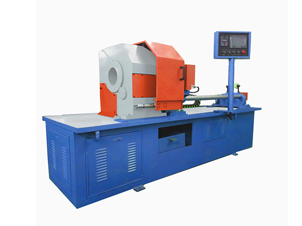
A pipe cutting lathe machine used in conveyor roller manufacturing performs a very different function from a conventional pipe cut-off machine. The raw steel pipe has normally already been separated into a defined roller-shell blank before it reaches this stage. The lathe then machines the two tube ends so they have the geometry required for bearing housings, later assembly, and consistent roller production.
This distinction is important because simply cutting a tube to length does not create the finished end structure needed by a conveyor roller. The cut face may still contain dimensional variation, burrs, or an end condition that is unsuitable for accurate bearing-seat preparation. Double-end machining establishes a more controlled reference at both sides of the roller shell.
For batch production, processing both ends within one machine setup also reduces repeated workpiece repositioning. The tube can be clamped once while synchronized left and right machining units feed toward the workpiece, machine the required geometry, and retract after the operation is complete.
What Is a Pipe Cutting Lathe Machine in Roller Production?
In this application, a pipe cutting lathe machine is specialized equipment for machining the ends of steel pipe used in conveyor rollers. It should not be confused with a machine whose main purpose is cutting long pipe stock into shorter lengths.
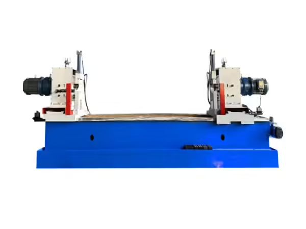
The existing Automatic Roller Double End Holes Lathe is designed specifically for belt conveyor steel pipe. Mechanical fast clamping secures the tube, hydraulic systems control cutter feed, and the left and right feed cylinders operate through a synchronized hydraulic circuit.
Both ends can therefore be machined within the same setup. This structure is particularly suitable for repeated roller-shell production because corresponding end features need to maintain a controlled relationship with the same tube centerline and overall blank length.
Why Tube-End Machining Comes After Pipe Cutting
Roller-shell production normally begins by dividing long steel pipe into blanks. That first operation establishes the approximate finished length, but it does not necessarily create the precise end geometry needed for later roller assembly.
The pipe cutting lathe machine takes the already-cut blank and refines both ends. This creates more predictable surfaces and dimensional references for bearing-related components.
Separating these operations also makes process control clearer. The cut-off machine is responsible for producing consistent blanks, while the double-end lathe is responsible for creating the required end geometry.
When both machines perform their defined tasks consistently, downstream assembly receives a more stable workpiece.
Double-End Machining Reduces Repositioning
Processing one tube end at a time requires the workpiece to be removed, reversed, repositioned, and clamped again before the opposite side can be completed.
Every additional setup introduces another opportunity for variation. The tube may not return to exactly the same centerline, clamping force can change, and the relationship between the two machined ends becomes more dependent on operator positioning.
A double-end pipe cutting lathe machine avoids much of this repeated datum transfer. Both cutting units work around one clamped tube, allowing corresponding end features to remain related to the same workpiece setup.
This is particularly valuable when many roller shells of the same specification are being produced in one batch.
TC-220×2200 Working Range
The TC-220×2200 configuration covers a broad range of conveyor roller steel-pipe dimensions.
| Technical Item | TC-220×2200 Reference |
|---|---|
| Steel pipe diameter | Φ76–219 mm |
| Steel pipe length | 200–2200 mm |
| Processing depth at both ends | 0–70 mm |
| Cutting depth | 0–3 mm |
| Spindle center height | 900 mm |
| Main spindle speed | 500 r/min |
| Tool-holder radial scale | 0.05 mm |
| Radial repeat positioning | 0.05 mm |
| Hydraulic working pressure | 2.5–4 MPa |
| Main drive motor | 4 kW |
| Clamp motor | 1.5 kW |
These values define the machine envelope, but the actual roller drawing still determines the correct machining dimensions. Tube diameter, blank length, required end depth, bearing-housing structure, and following assembly process all need to be considered together.
Pipe Diameter Changes the End-Machining Setup
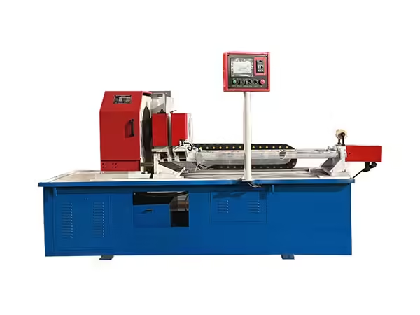
A Φ76 mm roller shell and a Φ219 mm roller shell present substantially different geometry to the cutting tools.
The cutting units need to reach the required machining position while maintaining a predictable relationship with the tube centerline. Clamping also needs to accommodate the larger or smaller outside diameter without allowing the workpiece to shift during cutting.
Machine setup should therefore change systematically when the roller diameter changes. Tool position, clamping condition, and required cutting depth should all be confirmed from the workpiece specification.
The first completed tube after a diameter change provides an important verification that the new setup matches the physical workpiece.
Tube Length Requires Correct Machine Positioning
The machine supports roller-shell lengths from approximately 200 to 2200 mm. This range means the distance between machining units needs to adapt to substantially different workpieces.
Longer tubes also require suitable support so the workpiece remains close to the intended machine centerline during clamping and machining.
If a long tube sags or sits unevenly, both ends may no longer align with the cutting units in the same way. Workpiece support therefore contributes directly to end-machining consistency.
Length should be treated as part of the complete machine setup rather than simply as a dimension that determines spindle spacing.
Mechanical Fast Clamping Stabilizes the Workpiece
The machine uses a mechanical fast-clamping device designed to hold the steel pipe securely during processing.
Clamping force can be adjusted according to the workpiece, which is important because the tube needs to remain stable without being positioned inconsistently from one cycle to the next.
A clamping system does more than prevent longitudinal movement. It also helps establish the physical relationship between the tube and the two machining heads.
Contact surfaces should remain clean and correctly adjusted because chips or wear around the clamp can gradually change how the workpiece sits inside the machine.
Hydraulic Feed Controls Both Machining Ends
The left and right cutting units use hydraulic feed, with a synchronized hydraulic loop allowing both feed cylinders to advance and retract together.
This structure helps both tube ends follow the same general machining sequence. Instead of relying on two unrelated manual feed operations, the machine coordinates the movement of both sides.
Hydraulic stepless speed regulation also allows the feed condition to be adapted to the machining requirement.
Stable hydraulic pressure is therefore part of process consistency. Leaks, valve problems, or pressure variation can influence machine movement even if all mechanical settings remain unchanged.
Radial Tool Adjustment Provides Fine Control
The machine combines automatic hydraulic feed with manually adjustable radial tool positioning.
The tool-holder radial feed scale is approximately 0.05 mm per division, while radial repeat-positioning accuracy is also listed at approximately 0.05 mm.
This fine adjustment is useful because tube-end machining often requires dimensional control around bearing-related features rather than simple rough material removal.
The operator can therefore establish the radial position according to the roller specification, while the machine performs the main synchronized feed cycle automatically.
Measurement of the finished workpiece should still confirm that the physical result matches the intended tool setting.
Automatic Tool Relief Protects the Machined Surface
One useful feature of the machine is its hydraulic automatic tool-relief mechanism. After the cutter reaches the predetermined machining position, the system can automatically withdraw the tool before return movement.
This helps reduce the possibility of the cutter scratching the newly machined surface during retraction.
The principle is important because the finished end surface has already become a dimensional and functional reference by this stage of the cycle.
Protecting the machined area during return movement supports more consistent surface condition and reduces unnecessary rework.
How Turning Differs From Pipe Cut-Off
Turning is a machining process in which cutting tools remove material from a rotating or otherwise controlled workpiece geometry to create defined surfaces. In specialized roller-processing machinery, the cutting relationship is adapted to the tube and machine structure.
Pipe cut-off, by contrast, primarily separates one length of material from another. The objective is blank creation rather than finished end geometry.
This difference explains why a roller factory can require both an automatic pipe-cutting machine and a double-end lathe. The two machines solve different manufacturing problems and should not be treated as interchangeable equipment.
End Depth Determines the Machined Region
The TC-220×2200 supports processing depths at both ends from approximately 0 to 70 mm.
This range allows different roller-shell designs to be machined according to the depth required by their internal components.
The correct value should always come from the finished roller drawing. Removing more material than necessary does not improve the part and can change the geometry available for the bearing housing or other assembly components.
Tool feed and radial position therefore need to be established together so the cutter removes material only from the intended region.
Cutting Depth Influences Tool Load
The listed cutting-depth range is approximately 0–3 mm.
Cutting depth affects how much material the tool removes during each machining pass and therefore influences cutting force, tool condition, and finished surface.
A deeper cut should not automatically be used simply to reduce machining time. The correct value depends on tube material, dimensional allowance, cutter condition, spindle behavior, and required final geometry.
Stable machining comes from balancing these variables rather than maximizing one setting independently.
Why Spindle Speed Matters
The main shaft operates at approximately 500 r/min in the listed TC-220×2200 configuration.
Spindle speed works together with cutting depth, tool geometry, and feed condition to determine the machining environment.
Changes in tube diameter or material can influence how the cutter behaves even if spindle speed remains unchanged.
For repeated roller specifications, validated operating settings provide a useful baseline. The machine can then return to known conditions when the same tube family enters production again.
End Geometry Supports Bearing-Housing Assembly
One of the primary reasons for machining roller-shell ends is to prepare the tube for the components installed later in the production process.
Bearing housings need predictable tube geometry so they can be positioned consistently relative to the shell centerline.
If one tube end contains excessive dimensional variation, the housing may no longer sit in the same relationship as the component at the opposite end.
Double-end machining therefore helps create a stronger foundation for later bearing setting and welding.
Cast and Stamped Bearing Housing Compatibility
The Automatic Roller Double End Holes Lathe is designed for rollers using either cast-iron bearing seats or punched/stamped bearing housings.
These structures may require different machining dimensions, but both depend on the steel pipe being prepared according to the corresponding roller design.
This flexibility makes machine setup important. The workpiece should not be machined according to a generic end condition when the following bearing-housing structure changes.
The roller drawing should identify the required tube-end geometry so machining remains connected with the actual assembly.
How the Machine Fits Into the Roller Production Sequence
The pipe cutting lathe machine belongs between tube blank preparation and later roller assembly.
The broader Manufacturing and Processing Machinery range includes automatic tube-cutting equipment, double-end tube machining, roller shaft processing, bearing setting, and automatic welding machinery.
These machines perform separate but connected operations. Tube cutting establishes the blank, the double-end lathe creates controlled end geometry, assembly machines position internal components, and welding secures the completed roller structure where required.
The production route becomes more stable when every stage receives a predictable workpiece from the operation before it.
Connection With Automatic Tube Cutting
Automatic tube cutting creates the initial shell blank. Its most important outputs are consistent length and a suitable end condition.
The double-end lathe then refines this workpiece rather than replacing the cutting operation.
If tube blanks vary significantly in length, the lathe receives inconsistent starting workpieces. This can change machining allowance and make later dimensional control more difficult.
Upstream cutting consistency therefore improves the stability of the lathe operation.
Connection With Bearing Setting
After tube-end machining and other required preparation, bearing-related components can be positioned within the roller assembly.
A bearing-setting process depends on the geometry established earlier. If the tube ends are machined inconsistently, component positions may differ between rollers even when the press-fitting machine follows the same cycle.
This demonstrates why machine accuracy should be considered across the production chain rather than only within individual pieces of equipment.
A controlled pipe cutting lathe machine provides the next assembly stage with a more predictable shell.
Connection With Double-End Welding
Certain steel roller constructions use welding around the tube ends after components have been positioned.
Welding quality depends partly on joint consistency. If the tube end and installed components are located differently from one roller to another, the welding heads receive joints in different positions.
Stable end machining therefore indirectly supports automatic welding by improving the repeatability of the geometry arriving at that later stage.
Each manufacturing operation creates the reference condition needed by the next.
Why Batch Roller Production Benefits From Double-End Machining
The machine is especially suitable for batch roller manufacturing because the same machining cycle can be repeated across many steel-pipe blanks.
Once the workpiece specification has been established, clamping, radial tool position, hydraulic feed, and cutting depth can remain controlled around the same product family.
This reduces the repeated manual setup associated with machining each end separately.
The benefit is not simply increased output. More importantly, the process can reproduce a known dimensional relationship across multiple roller shells.
First-Piece Inspection After Setup Changes
Any significant change in tube diameter, length, bearing-housing design, cutter position, or processing depth should be followed by first-piece inspection.
The completed tube should be checked for required diameter, end depth, surface condition, correspondence between left and right ends, and any dimensions needed by the following assembly stage.
If the first piece does not match the drawing, adjustments can be completed before continuous production begins.
This is especially important in batch manufacturing because automated or semi-automatic equipment can reproduce an incorrect setup repeatedly once the cycle starts.
Comparing Left and Right End Results
A double-end machine provides an immediate opportunity to compare corresponding machined areas on the same tube.
If one side repeatedly differs from the other, the problem can often be narrowed to one machining head, cutter, hydraulic circuit, or radial adjustment.
If both sides change similarly, a shared factor such as raw tube dimensions, clamping, or hydraulic condition may deserve closer inspection.
Recording left and right dimensions separately can therefore provide more useful troubleshooting information than recording only one general result.
Diagnosing End-Diameter Variation
If the finished machining diameter begins to change during a batch, operators should first check cutter position, radial adjustment, tool wear, and workpiece centering.
Tube outside-diameter variation before machining can also affect the amount of material removed.
Changing the machine setting without identifying the cause may temporarily correct one dimension while introducing another process inconsistency.
A structured check of incoming material, machine position, and tooling provides a more reliable troubleshooting sequence.
Diagnosing Unequal Machining Depth
Differences in left and right processing depth can originate from workpiece location, feed-cylinder movement, cutter setup, or the original tube length.
Because both ends are intended to operate through a synchronized hydraulic system, a consistent difference between sides deserves closer inspection.
The workpiece should first be confirmed against the raw blank specification before machine adjustments are made.
This prevents the machine from being used to compensate for variation already introduced during the previous tube-cutting operation.
Diagnosing Poor Surface Finish
Poor surface condition can result from tool wear, unsuitable cutting depth, vibration, spindle condition, unstable clamping, or workpiece-material variation.
The first troubleshooting step should be determining whether the issue appears at both ends or only one side.
A single-side problem can indicate cutter or spindle condition on that machining unit, while a similar problem at both ends may point toward the material or shared setup.
Tool condition should be inspected before cutting parameters are changed extensively.
Tool Wear Should Be Monitored During Production
Cutting tools change gradually as material is removed from repeated steel-pipe workpieces.
A tool can continue machining even after its edge condition has begun to influence dimensional stability or surface quality.
Monitoring burr formation, machining sound, surface finish, and measurement results can therefore provide earlier indications of wear than waiting for complete tool failure.
Tool servicing or replacement should then be followed by first-piece verification because a fresh cutting edge can alter the machining result relative to the worn tool it replaced.
Hydraulic-System Maintenance
The hydraulic system controls important feed movements, making pressure stability an important part of machining consistency.
The listed operating pressure is approximately 2.5–4 MPa. Hoses, valves, seals, hydraulic fluid, and related components should therefore be inspected according to normal machine maintenance requirements.
Leaks or irregular movement can influence the synchronized left-right feed condition.
Changes in cycle behavior should be investigated early rather than waiting for visible dimensional variation to appear in completed tubes.
Clamp Maintenance
The mechanical fast clamp repeatedly establishes the workpiece position.
Contact surfaces should remain clean and free of chips. Adjustment components should remain secure, and the clamping mechanism should move consistently.
Different pipe diameters can require different clamping adjustments, so production changeovers deserve additional attention.
A stable clamp gives both cutting units a predictable workpiece reference before machining begins.
Spindle and Tool-Holder Maintenance
The spindles and tool holders determine the relationship between the cutting edges and the steel pipe.
Mechanical looseness, abnormal vibration, worn bearings, or insecure cutter mounting can gradually reduce machining stability.
Both machining sides should be inspected because corresponding features are produced at the same time.
Comparing the two units provides a useful way to identify whether developing variation is localized or shared across the machine.
Common Mistake: Confusing Cut-Off With End Machining
The phrase pipe cutting lathe machine can easily be misunderstood as equipment used only to separate long pipe stock.
In this roller-production application, however, the double-end lathe processes the ends of already-cut steel-pipe blanks. Its function is precision end preparation rather than raw-material cut-off.
Keeping this distinction clear prevents two separate manufacturing stages from being treated as competing machine options.
A roller factory can legitimately require both types of equipment because they perform sequential operations.
Common Mistake: Checking Only Overall Tube Length
Overall blank length is important, but it does not describe the finished tube-end geometry.
Machined depth, radial dimensions, left-right consistency, and surface condition also influence how the tube accepts bearing-related components later in production.
Inspection should therefore follow the dimensional features created by the lathe rather than measuring only the workpiece length.
The complete roller drawing provides the best reference for these requirements.
Common Mistake: Ignoring Upstream Variation
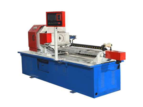
A double-end lathe cannot automatically correct every problem created by the tube-cutting operation.
If blanks arrive with inconsistent length, severe angular end faces, or unsuitable raw dimensions, the lathe has to process different starting conditions during every cycle.
Upstream cutting should therefore be stabilized before repeated adjustments are made to the end-machining machine.
Controlling the full production chain is more effective than expecting one downstream machine to compensate for earlier variation.
Practical Process-Control Matrix
| Process Area | Key Control |
|---|---|
| Incoming tube | Diameter, blank length, end condition |
| Clamping | Stable tube position |
| Left/right machining | Synchronized feed |
| Radial tool position | Required end dimensions |
| Processing depth | Match roller drawing |
| Cutting tool | Wear and mounting |
| Hydraulic system | 2.5–4 MPa stable operation |
| Tool relief | Protect machined surface |
| Inspection | Compare both ends |
| Downstream assembly | Confirm housing compatibility |
Using these control points together makes it easier to maintain a predictable transition from tube cutting to roller assembly.
Conclusion
A pipe cutting lathe machine used in conveyor roller manufacturing should be understood as a tube-end machining system rather than a conventional pipe cut-off machine. The raw roller-shell blank has already been cut to length before it reaches this stage; the lathe then creates controlled geometry at both steel-pipe ends for the manufacturing operations that follow.
The TC-220×2200 configuration supports approximately Φ76–219 mm steel pipe and 200–2200 mm workpiece lengths. Mechanical fast clamping stabilizes the tube, hydraulic synchronized feed processes both sides, radial tool adjustment provides fine dimensional control, and automatic tool relief helps protect the completed surface during retraction.
Reliable production still depends on consistent incoming blanks, stable clamping, cutter condition, hydraulic maintenance, first-piece verification, and comparison between both machined ends. When these factors are controlled together, double-end tube machining creates a stronger dimensional foundation for bearing assembly, welding, and final conveyor roller production.
FAQ
What is a pipe cutting lathe machine used for in conveyor roller production?
In this application, a pipe cutting lathe machine processes the two ends of already-cut steel-pipe blanks used for conveyor rollers. It does not primarily separate long raw pipe into sections. Instead, it creates controlled end geometry so bearing housings and later roller components can be positioned more consistently during assembly.
What pipe sizes can the TC-220×2200 process?
The TC-220×2200 supports steel-pipe outside diameters of approximately Φ76–219 mm and workpiece lengths from 200 to 2200 mm. Processing depth at both ends can reach approximately 70 mm, while cutting depth is listed from 0 to 3 mm depending on the required roller-shell geometry.
Why does the machine process both pipe ends at the same time?
Double-end machining keeps both ends related to the same workpiece setup and reduces the need to reverse and reclamp the steel pipe. Synchronized hydraulic feed allows the left and right cutting units to advance and return together, supporting more consistent end geometry during repetitive roller production.
How is a double-end lathe different from an automatic pipe cutting machine?
An automatic pipe cutting machine divides long raw steel pipe into shorter roller-shell blanks. The double-end lathe operates afterward and machines the ends of those blanks to create more controlled geometry for bearing-related assembly. The two machines therefore perform sequential but different manufacturing operations.
What should be inspected after double-end pipe machining?
Inspection should verify the dimensions created at both tube ends, machining depth, radial dimensions, surface condition, and left-right consistency. The incoming blank length and tube diameter should also be checked because variation from the previous cutting stage can influence the amount of material removed during end machining.
 English
 French
 Spanish