

Table of Contents
Introduction
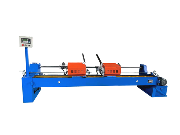
Shaft-end preparation is a relatively small part of conveyor roller manufacturing, but several later operations depend on the geometry established at this stage. A roller shaft may require a controlled end face, a chamfer around the outer edge, and an accurately positioned center hole before it proceeds into additional machining or final assembly. When these features are created through several independent setups, every transfer between machines introduces another opportunity for workpiece positioning variation.
A chamfer cutting machine designed specifically for long shaft products can integrate these operations into one coordinated process. Instead of finishing one shaft end, reversing the workpiece, and establishing a new reference for the opposite side, a double-end machine keeps both ends related to the same shaft centerline while machining occurs simultaneously.
This article explains how flat-head machining, chamfering, center-hole preparation, automatic clamping, double-end processing, tooling, PLC control, and dimensional inspection work together in conveyor roller shaft production.
What Is a Chamfer Cutting Machine for Roller Shafts?
A chamfer cutting machine for roller shaft production is specialized equipment that prepares the ends of long cylindrical shafts rather than simply removing a sharp edge. The machine needs to hold the workpiece accurately, maintain its centerline, position cutting tools at both ends, and produce several related geometric features within one stable setup.
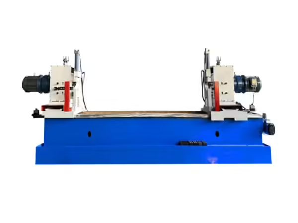
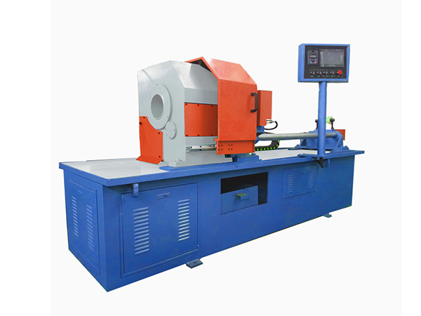
The existing Flat Head Chamfer Playing Center Hole Machine Tool completes center-hole machining, flat-head processing, and chamfering at both ends simultaneously. Automatic feeding, clamping, tool advance, and tool return are coordinated through PLC control.
This makes the machine particularly relevant to conveyor roller shaft manufacturing, where opposite ends often contain corresponding features and where dimensional relationships between those ends need to remain consistent across repeated production.
Why Flat Head, Chamfer, and Center Hole Belong Together
Flat-head machining, chamfering, and center-hole preparation perform different functions, but they are all related to the same shaft-end geometry.
The flat end face establishes a dimensional reference and influences final shaft length. The chamfer removes the sharp edge and creates a defined transition between the shaft outside diameter and end surface. The center hole establishes a reference around the shaft axis that can support later machining or positioning operations.
Completing these operations within one setup helps maintain their geometric relationship. If each feature is produced on another machine, the shaft must be relocated repeatedly, and every relocation creates a new opportunity for variation.
Integrated processing therefore improves process organization by treating the shaft end as one complete geometric system.
How Chamfering Changes the Shaft Edge
A chamfer is a beveled transition between two surfaces. On a roller shaft, it replaces the sharp intersection between the cylindrical outside surface and the end face with a controlled angled edge.
This feature can improve handling and provide a more predictable lead-in for later assembly or machining. The important point is that an industrial chamfer should be defined by the technical drawing rather than produced simply until the edge “looks smooth.”
Chamfer geometry is connected with shaft diameter and end-face position. Excessive material removal changes the finished geometry, while insufficient machining can leave the original sharp transition partly intact.
For batch production, machine-controlled chamfering provides a repeatable method for reproducing the same edge condition on many shafts.
Flat-Head Machining Establishes the End Reference
Before a shaft end can act as a reliable dimensional reference, its end face needs to be controlled.
Flat-head machining removes material from the shaft end to create a defined surface. The resulting position influences overall shaft length and can provide a reference from which nearby features are measured.
When both ends are processed simultaneously, the machine can manage the left and right surfaces within the same shaft setup. This reduces the amount of dimensional variation introduced through repeated repositioning.
The process is particularly useful when the shaft later receives grooves, flats, or other features whose location is related to the finished end face.
Why Center Holes Need Accurate Positioning
A center hole is useful only when it corresponds closely with the intended shaft axis. If it is offset from the centerline, later processes using the hole as a locating or machining reference may inherit that positional error.
For this reason, center-hole machining should not be viewed as a simple drilling operation independent from the rest of the shaft.
The workpiece needs to be centered and clamped before the cutting unit advances. Once the shaft centerline has been established, corresponding center holes at both ends can be produced around the same workpiece reference.
Combining this operation with flat-head and chamfer machining further reduces the need to recreate the shaft centerline in another setup.
TPD-2040 Working Range
The TPD-2040 is designed specifically around long shaft products with relatively small diameters.
| Technical Item | TPD-2040 Reference |
|---|---|
| Processing diameter | Φ20–40 mm |
| Processing length | 280–2200 mm |
| Working accuracy | ±0.1 mm |
| Working pressure | 4–8 MPa |
| Control method | PLC |
| Main operations | Flat head, chamfer, center hole |
| Processing position | Both ends simultaneously |
| Material handling | Automatic loading/unloading available |
These values define the basic machine envelope, but the actual workpiece drawing still determines the correct setup. Shaft material, end geometry, chamfer requirement, center-hole dimensions, and processes before and after this operation also need to be considered.
Why Double-End Processing Matters
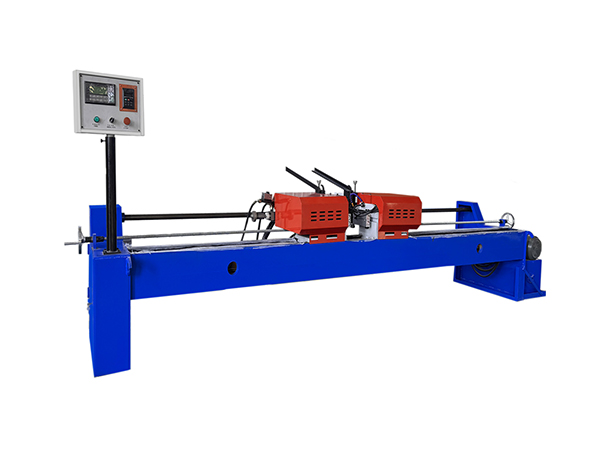
Long conveyor roller shafts normally contain corresponding geometry at both ends. Processing one side independently and then reversing the shaft requires a second positioning operation, which can change the relationship between the workpiece and the cutting system.
A double-end chamfer cutting machine positions the shaft once while machining units work from opposite directions. Both end faces, chamfers, and center holes therefore remain related to the same basic workpiece setup.
This structure is particularly valuable during repetitive production. The machine can reproduce the same sequence across many shafts without requiring the operator to manually recreate the second-end reference on every component.
The advantage is not only faster handling. It also reduces the number of datum transfers inside the machining process.
Shaft Centerline Is the Main Geometric Reference
The machine needs to maintain a stable relationship between the shaft centerline and cutting plates throughout the machining cycle.
If a shaft sits too high, too low, or off-center, the two end-processing units may engage the workpiece differently even when their mechanical settings remain unchanged.
Automatic positioning and clamping therefore form part of machining accuracy. They establish the workpiece condition before the cutting tools begin to move.
The incoming shaft also matters. Severe straightness variation or inconsistent raw dimensions can change how the workpiece sits inside the fixture, which means automatic equipment still benefits from controlled input material.
Automatic Clamping Reduces Setup Variation
After the shaft reaches its machining position, the clamping system needs to hold it securely while both cutting units complete their movements.
Automatic clamping creates a repeatable sequence instead of requiring the operator to manually secure every workpiece. The objective is to maintain shaft position without allowing movement during end facing, chamfering, or center-hole processing.
Clamping surfaces should remain clean because chips or other contamination can alter the position of the next workpiece. Mechanical wear and pressure stability should also be inspected during routine maintenance.
A consistent clamping process provides the foundation for repeatable machining rather than simply serving as a workholding convenience.
PLC Control Coordinates the Complete Cycle
The machine uses PLC control to coordinate automatic feeding, clamping, double-end cutting movement, tool return, and related machine actions.
This is important because several operations need to happen in the correct sequence. The workpiece should not enter cutting until it has been positioned and secured, while unloading should begin only after both cutting units have returned safely.
Automation makes it possible to repeat the same general cycle across a batch of similar shafts. However, it does not eliminate the need for correct tooling, stable pressure, accurate fixtures, or dimensional inspection.
The control system reproduces machine commands consistently; the mechanical system determines how accurately those commands are converted into finished geometry.
Standardized Blades Simplify Tool Control
The machine uses a specially designed cutting plate with standardized blades, allowing blade adjustment and replacement to be handled more systematically.
Tool standardization can be useful in batch production because it reduces variation associated with individually prepared cutting edges. When a worn blade needs attention, the cutting component can be adjusted or replaced without rebuilding the complete tool arrangement.
Blade wear should still be monitored through the finished workpiece. Increasing burr formation, rougher end faces, changing chamfer quality, or unusual machining sound can indicate deterioration even when the machine continues completing its programmed cycle.
Tool condition therefore remains part of dimensional process control.
Working Accuracy Depends on More Than the Machine Specification
The TPD-2040 lists working accuracy of approximately ±0.1 mm, but actual finished-part consistency depends on several connected factors.
Incoming shaft dimensions, workpiece straightness, positioning, clamping, cutter condition, machine alignment, pressure stability, and inspection methods can all influence the physical result.
This means the accuracy specification should not be interpreted as something the control system produces regardless of production conditions.
A stable process combines capable equipment with controlled workpieces and validated setup methods. First-piece measurement then confirms whether the machine and actual shaft are producing the intended geometry together.
First-Piece Inspection After Every Major Change
A first-piece inspection should be performed whenever shaft diameter, length, blade condition, chamfer requirement, center-hole specification, or another significant setup variable changes.
Useful checks include overall finished shaft length, left and right end-face position, chamfer geometry, center-hole position, surface condition, and visible burr formation.
The first component provides direct evidence that the new setup is producing the intended result. If adjustment is required, it can be completed before the same condition is reproduced throughout the batch.
This is particularly important with automatic machinery because repeatability multiplies incorrect settings just as efficiently as correct ones.
Comparing Both Shaft Ends Provides Useful Process Data
A double-end machine creates two corresponding machining results on the same workpiece. This provides a useful internal reference for production inspection.
If the left and right chamfers consistently differ, the two cutting units, tool positions, blades, workpiece supports, and machine adjustments can be compared directly.
If both ends change in the same direction, a shared condition such as shaft diameter, workpiece positioning, pressure, or incoming material may deserve closer inspection.
Recording left and right measurements separately therefore provides more diagnostic value than recording only one overall result.
Diagnosing Uneven Chamfer Geometry
Uneven chamfers can result from workpiece centering, blade position, blade wear, shaft diameter variation, or differences between the two cutting units.
Troubleshooting should begin with the physical workpiece position before control values are changed. Shaft centerline and clamping need to be confirmed first because incorrect positioning affects several machining features simultaneously.
The cutting tools should then be inspected for wear and adjustment.
This sequence reduces the risk of changing machine settings to compensate for a problem that actually originates from tooling or workpiece positioning.
Diagnosing Inconsistent Finished Shaft Length
Because flat-head machining removes material from both ends, the process influences the final end-to-end shaft dimension.
If completed shafts begin showing length variation, the incoming raw length, shaft positioning, cutting-unit movement, clamping condition, blade wear, and machine references should all be reviewed.
Both ends contribute to the final dimension, so troubleshooting should not automatically focus on only one cutting unit.
When the change appears gradually during a long batch, tool wear or mechanical movement may be more likely than an incorrect initial program.
Diagnosing Center-Hole Offset
An offset center hole suggests that the relationship between the shaft axis and cutting unit needs to be examined.
Workpiece centering, clamping, shaft straightness, cutting-tool position, and machine alignment should be checked before assuming the center-hole tool itself is the only cause.
If one end repeatedly shows the problem while the opposite side remains stable, inspection can focus on the corresponding machining unit.
When both ends show similar offset, the shared workpiece locating system may deserve greater attention.
Where Chamfer Cutting Fits in Roller Shaft Production
A roller shaft may require several processing stages before final assembly. Flat-slot milling, through-flat milling, circlip grooving, end preparation, and other operations are selected according to the finished shaft design.
The broader Manufacturing and Processing Machinery range includes dedicated equipment for these individual stages rather than relying on one universal machine to create every shaft feature.
Chamfer cutting therefore needs to be placed at the correct point in the process sequence. Operations before it should provide a stable shaft, while later operations should preserve the end geometry already established.
The final component drawing should determine the sequence rather than a fixed rule applied to every roller shaft.
Relationship With Flat Milling
Flat milling creates mounting surfaces on the shaft, while chamfering prepares the shaft end. These operations remove material from different areas and perform different mechanical functions.
When both features are required, their dimensional references should remain connected. Flat position may be defined from the shaft end, which means inconsistent end facing can influence how later measurements are interpreted.
For this reason, the machining route should identify which feature establishes the reference for the next operation.
Dedicated equipment makes the process easier to control because each machine is responsible for a clearly defined part of the shaft geometry.
Relationship With Circlip Grooving
Circlip grooves create retaining positions along the shaft, while flat-head and chamfer machining establish the end condition.
If groove position is dimensioned from the finished end face, the consistency of flat-head processing becomes directly relevant to the grooving operation.
A stable shaft-end reference therefore makes later groove-position control more predictable.
This relationship illustrates why shaft machining should be planned as one connected process instead of a collection of unrelated operations.
Automatic Loading and Unloading in Batch Production
Automatic loading and unloading can support repetitive production when many shafts of the same specification need to pass through the machine.
The benefit comes from creating a consistent material-flow sequence around the machining cycle. The shaft enters the work position, is located and clamped, receives double-end processing, and then leaves the machine for the next manufacturing stage.
Material handling should still maintain shaft condition. Long workpieces need suitable support so they do not arrive at the machining position under unnecessary bending or misalignment.
Automation works best when both machining and material movement are designed around the same shaft geometry.
Why Machine Rigidity Matters
Although the machine is not performing heavy rough milling, its structure still needs to maintain the relationship between both cutting units and the workpiece throughout the cycle.
Movement or looseness in fixtures, cutting plates, supports, or machine components can alter the geometry produced at the shaft ends.
Long shafts make this relationship particularly important because small positional differences between the two ends can become more apparent across the full workpiece length.
Routine inspection should therefore consider mechanical fastening and machine condition as well as tool wear.
Maintenance of the Clamping System
The clamping system repeatedly establishes the physical position of every shaft processed by the machine.
Contact surfaces should remain clean, and actuating components should move consistently. Any looseness, uneven wear, or pressure-related problem can change the workpiece position without altering the PLC program.
Machines processing several shaft diameters also require attention around adjustment points because repeated changeovers can gradually introduce mechanical variation.
Maintaining stable clamping helps preserve the common centerline needed for all three shaft-end operations.
Maintenance of Cutting Plates and Blades
Cutting plates and blades directly influence end-face quality and chamfer geometry, so they should be included in preventive inspection.
Operators can monitor finished components for changes in surface appearance, burr formation, machining sound, or dimensional results. These observations provide useful information about tool condition before wear becomes severe.
Blade replacement should then be followed by first-piece verification because a new cutting edge can change the machining condition relative to the worn tool it replaced.
Tool maintenance and dimensional inspection should therefore operate as one connected control process.
Avoid Confusing Shaft Chamfering With Tube Chamfering
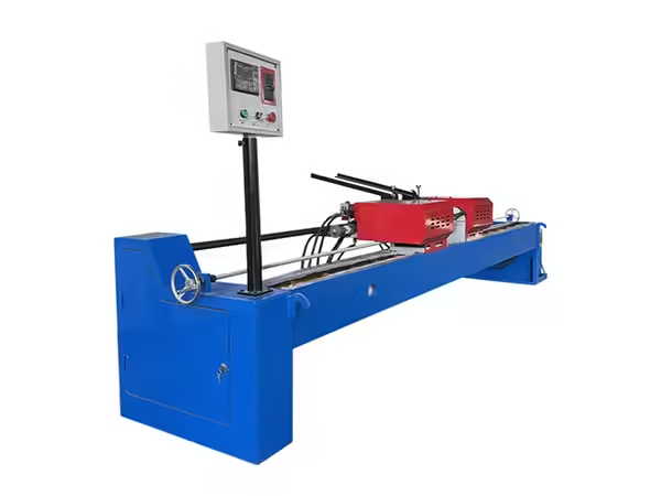
The machine discussed here is mainly designed for shaft products. This distinction is important because shaft-end processing and tube-end processing involve different workpiece geometry and manufacturing requirements.
A hollow tube can require another type of support, clamping, and edge preparation from a solid or shaft-type workpiece. Using a broad “chamfering machine” label without identifying the material shape can therefore create incorrect equipment expectations.
For conveyor roller production, this chamfer cutting machine should be understood specifically as a shaft-end processing system integrating facing, chamfering, and center-hole machining.
Keeping this application precise prevents the equipment from being confused with unrelated tube-processing machinery.
A Practical Process-Control Matrix
Stable shaft-end machining depends on several related production variables.
| Process Area | Main Control Point |
|---|---|
| Incoming shaft | Diameter, length, straightness |
| Positioning | Shaft centerline |
| Clamping | Stable workpiece location |
| Flat-head machining | End position and surface |
| Chamfering | Defined edge geometry |
| Center hole | Position relative to shaft axis |
| Cutting blades | Condition and adjustment |
| Pressure | Stable 4–8 MPa operating range |
| PLC cycle | Correct machining sequence |
| Inspection | First piece and periodic verification |
The matrix shows why no single machine specification determines the quality of the completed shaft.
Conclusion
A chamfer cutting machine used in conveyor roller manufacturing should do more than remove sharp shaft edges. The process needs to control the complete shaft-end geometry, including the flat end face, chamfer, and center hole, while maintaining a stable relationship between corresponding features at both ends.
The TPD-2040 is designed for shaft diameters of approximately Φ20–40 mm and lengths from 280 to 2200 mm, with listed working accuracy of ±0.1 mm and PLC-based automatic operation. Double-end simultaneous machining reduces repeated repositioning, while standardized cutting blades and automatic material handling support repetitive shaft production.
Reliable results still depend on stable incoming material, correct centering, clamping, tool condition, machine maintenance, and dimensional verification. When these factors are controlled together, flat-head, chamfer, and center-hole processing can become one repeatable stage within the broader conveyor roller shaft manufacturing process.
FAQ
What is a chamfer cutting machine used for in conveyor roller production?
A chamfer cutting machine for conveyor roller production prepares shaft ends by creating defined chamfers and can also combine flat-head and center-hole machining. The equipment is designed around long shaft workpieces so corresponding features at both ends can remain related to the same centerline and machining setup.
What shaft sizes can the TPD-2040 process?
The TPD-2040 is designed for shaft diameters of approximately Φ20–40 mm and processing lengths from 280 to 2200 mm. Its listed working accuracy is approximately ±0.1 mm, and it uses PLC control with automatic feeding, clamping, and double-end machining movements.
Why combine flat-head, chamfer, and center-hole machining?
These features are all connected with shaft-end geometry. Processing them within one setup reduces repeated workpiece repositioning and helps maintain a more consistent relationship between the end face, chamfer, center hole, shaft length, and corresponding features at the opposite end.
Why is double-end machining useful for roller shafts?
Roller shafts normally contain corresponding geometry at both ends. Processing both sides simultaneously keeps them referenced to the same basic workpiece position and reduces the additional locating operation required when a shaft is reversed between separate single-end machining cycles.
What should be inspected after shaft-end chamfer cutting?
Inspection should check the finished shaft length, end-face condition, chamfer geometry, center-hole position, burr condition, and correspondence between the left and right ends. The first component after a setup or blade change deserves closer verification before continuous batch production begins.
 English
 French
 Spanish