

Table of Contents
Introduction
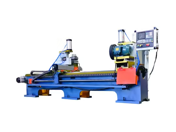
The conveyor roller shaft may appear to be a relatively simple component, but its end geometry plays an important role in roller assembly and installation. Depending on the roller design, a shaft may require flat surfaces, through flats, retaining-ring grooves, chamfers, center holes, or other machined features before it can move into the assembly stage.
A roller shaft processing machine is used to make these repetitive operations easier to control during batch manufacturing. Instead of repeatedly repositioning long shafts on general-purpose equipment, dedicated machines can process specific features at both ends through controlled clamping, feeding, milling, or grooving cycles.
For conveyor roller manufacturers, the objective is not simply to remove material from the shaft. The machining process needs to maintain consistent dimensions, symmetry between both ends, suitable surface condition, and compatibility with the components used during later roller assembly.
This guide explains the main roller shaft machining operations, how specialized equipment works, why double-end processing is useful, and what factors should be considered when building a stable shaft processing workflow.
What Is a Roller Shaft Processing Machine?
A roller shaft processing machine is specialized equipment used to machine the ends or surfaces of shafts used in conveyor rollers. The exact operation depends on the shaft design and can include flat milling, through-flat milling, circlip grooving, chamfering, center-hole preparation, and related processes.
These operations belong to the broader field of machining, in which controlled material removal is used to produce a workpiece with the required geometry and dimensions.
In roller production, dedicated machinery is useful because shafts are normally long cylindrical workpieces and often require similar features at both ends. The machine structure can therefore be designed specifically around shaft support, center height, double-end clamping, synchronized machining, and repetitive production.
A roller shaft processing machine may perform one specific operation or form part of a group of machines handling several shaft features before assembly.
Why Roller Shaft Geometry Matters
The shaft forms the central supporting element of a conveyor roller. While the outer tube rotates through the bearing arrangement, the shaft provides the connection between the roller and the conveyor structure.
For this reason, the dimensions and shape of the shaft ends need to correspond to the intended mounting arrangement.
A flat surface may provide a defined mounting position. A through-flat feature can help the shaft fit a particular bracket configuration. Circlip grooves can provide positions for retaining elements, while chamfers and center holes may support subsequent machining or assembly operations.
If these features vary significantly between workpieces, later assembly can become less predictable. Dimensional differences may influence component position, mounting symmetry, or the relationship between both ends of the roller.
Shaft machining should therefore be treated as a controlled manufacturing stage rather than a simple finishing process.
Main Processes in Conveyor Roller Shaft Machining
Different roller designs require different shaft features. A typical shaft processing workflow can include several operations.
| Processing Stage | Typical Feature | Main Purpose |
|---|---|---|
| Raw shaft preparation | Required shaft length | Establish starting workpiece |
| Flat milling | Flat surface on shaft end | Create defined mounting geometry |
| Through-flat milling | Extended flat section | Match conveyor mounting structure |
| Grooving | Circlip or retaining groove | Position retaining components |
| Chamfering | Beveled shaft end | Improve edge condition and preparation |
| Center-hole machining | Center reference | Support subsequent machining |
| Inspection | Dimensions and symmetry | Confirm machining consistency |
Not every shaft requires all of these processes. The correct sequence depends on the roller drawing and mounting structure.
The value of specialized machinery comes from matching the machine directly to the feature being produced.
Double-End Flat Milling for Roller Shafts

Flat milling is one of the common operations used on conveyor roller shafts. Material is removed from the cylindrical shaft end to create one or more controlled flat surfaces.
When these features are required on both ends, processing them separately can create additional handling and positioning steps.
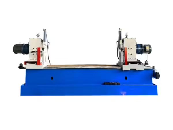
An automatic roller shaft double-end flat slot milling machine can process the required surfaces at both ends within one machine setup. The current equipment is designed specifically for belt conveyor roller shafts and can process four surfaces across both ends simultaneously.
This type of roller shaft processing machine supports batch production by reducing repeated shaft reversal and secondary positioning.
For the TX-2023 configuration shown on the website, the stated shaft diameter range is Φ20–40 mm and the shaft length range is 260–2300 mm, allowing the machine to handle a broad range of conveyor roller shafts.
Why Double-End Machining Is Useful
Long shaft workpieces create particular positioning challenges. When one end is processed first and the shaft is then reversed, the second operation depends on a new setup.
Every additional setup introduces another opportunity for dimensional variation.
Double-end machining allows both shaft ends to be referenced within the same machine structure. This can help maintain a more consistent relationship between corresponding features.
The benefit is especially relevant when the roller design requires symmetrical flats or grooves.
A double-end roller shaft processing machine can also reduce unnecessary handling. The shaft remains in one defined position while the two machining units work on opposite ends.
This does not remove the need for correct setup and inspection, but it creates a more repeatable foundation for batch processing.
Through-Flat Milling for Conveyor Roller Shafts
Some roller shafts require a through-flat configuration rather than a shorter flat groove. This feature changes the geometry of the shaft end and may be required to match the mounting structure used in a conveyor frame.
The automatic conveyor roller shaft double-end through flat milling machine uses a symmetrical double-spindle structure to process the shaft ends simultaneously.
The current machine is designed for shaft lengths from 300 to 2200 mm and diameters from 20 to 40 mm. Its double-spindle spacing can also be adjusted according to workpiece length.
Processing both ends in the same setup is particularly useful for this type of feature because the relationship between the left and right flats can be maintained through one controlled machine configuration.
Flat Slot Milling vs Through-Flat Milling
These two processes are related but should not be treated as identical.
Flat slot milling creates a defined flat section according to the shaft drawing. Through-flat milling produces a flat configuration extending through a specified section of the shaft end.
The correct process depends entirely on the roller design.
| Feature | Flat Slot Milling | Through-Flat Milling |
|---|---|---|
| Main geometry | Controlled flat area | Extended flat section |
| Typical workpiece | Roller shaft | Roller shaft |
| Double-end processing | Suitable | Suitable |
| Main selection basis | Shaft drawing | Shaft drawing |
| Key concern | Width, depth, symmetry | Width, depth, alignment |
A roller shaft processing machine should therefore be selected according to the actual required feature rather than simply by shaft diameter.
Circlip Groove Processing
Some roller shafts require grooves for retaining rings or circlips. Although these grooves occupy only a small area of the shaft, their position and dimensions need to correspond closely with the retaining component.
The groove must be produced at the correct distance from the shaft end and with the intended geometry.
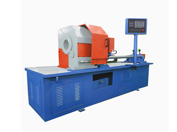
A dedicated conveyor roller shaft circlip grooving machine can process the grooves on both ends of the shaft within one setup. The current machine shown on the website is designed specifically for belt conveyor roller shafts and supports shaft diameters of 20–40 mm and lengths of 280–2200 mm.
Because the groove interacts with a retaining element during later assembly, repeatability is particularly important.
A groove that is too shallow, too deep, or incorrectly positioned may not provide the intended relationship between the components.
Why Dedicated Grooving Equipment Helps
Grooving can be carried out on general-purpose machine tools, but repeated production creates different requirements.
A dedicated machine can establish workpiece support, spindle movement, tooling position, and control logic specifically around the shaft groove.
Once the process has been adjusted for a particular shaft design, later workpieces can follow the same machining sequence.
This is valuable in roller manufacturing because large batches may contain shafts with identical dimensions.
The objective is not simply faster material removal. A more important advantage is reducing unnecessary setup variation between workpieces.
Chamfering and Shaft-End Preparation
Sharp shaft edges may need additional preparation before later manufacturing stages. Chamfering removes a controlled amount of material from the edge to create a beveled surface.
For roller shafts, chamfering can be combined with flat-head preparation or center-hole machining according to the required process.
Terok’s machine range includes equipment capable of completing center-hole machining, flat-head processing, and chamfering at both ends within the same working cycle.
Combining several shaft-end operations can simplify workpiece handling when those features are all required by the finished shaft design.
As with flat milling and grooving, the machining dimensions should always be based on the engineering drawing.
Center-Hole Machining in Shaft Production
A center hole can provide a reference point for later shaft machining. It may also support workpiece location in other manufacturing operations.
When center holes are required on both ends, their relationship to the shaft axis becomes important.
A machine that processes both ends in one setup can establish these features relative to the same workpiece position.
This is another example of why shaft manufacturing benefits from equipment designed around long cylindrical components.
The correct center-hole dimensions and subsequent use depend on the shaft design, so manufacturers should avoid treating center drilling as an isolated standard operation.
Workpiece Clamping Is Critical
Machining accuracy depends heavily on how the shaft is held during the cutting process.
The workpiece must remain stable as the milling cutter or grooving tool applies force. If the shaft moves, rotates unexpectedly, or shifts from its reference position, the finished dimensions can change.
Clamping should therefore provide sufficient stability without damaging the shaft surface.
For long shafts, support positions are also important. Improper support can allow the workpiece to sag or become incorrectly aligned relative to the machining heads.
A well-designed roller shaft processing machine combines workpiece supports, clamping devices, and machining units around a common centerline.
Hydraulic Systems in Roller Shaft Machines
Hydraulic systems are frequently used in specialized roller shaft machinery to control clamping and machining movement.
They can provide stable linear motion while allowing working speed to be adjusted according to the machining process.
The automatic double-end flat slot milling machine listed on the website uses a hydraulic system to control rapid spindle-box movement and machining feed. The circlip grooving equipment uses a similar structure for forward and return motion.
Hydraulic control can reduce repetitive manual movement, but the system still needs to operate together with suitable tooling, workpiece positioning, and machine alignment.
Pressure alone does not determine machining quality.
PLC Control and Batch Shaft Processing
A programmable logic controller can coordinate the sequence of machine operations.
In a roller shaft processing machine, PLC control may manage clamping, machining-head movement, travel limits, return movement, and other automated functions.
Once the machine has been configured correctly, the same operating logic can be repeated across multiple shafts.
This is useful for batch manufacturing because the operator does not need to recreate the machining sequence manually for every workpiece.
PLC control should still be supported by mechanical inspection and proper machine setup. If a tool becomes worn or a fixture moves from its intended position, repeating the same program will simply repeat the same process under changed mechanical conditions.
Tool Selection for Shaft Processing
Cutting tools need to match both the machining operation and the shaft material.
Flat milling, grooving, chamfering, and center-hole machining each use different cutting geometries.
Tool condition also influences dimensional stability and surface finish. As the cutting edge wears, machining forces may change and the finished feature may gradually become less consistent.
For batch production, tool inspection should therefore be integrated into the production routine.
Operators can monitor surface condition, machining dimensions, machine load, and visible tool wear to determine when closer inspection is required.
Shaft Diameter and Length Define Machine Range
A roller shaft processing machine should always be matched to the real product range.
Terok’s main dedicated shaft-processing machines generally target the common conveyor roller shaft diameter range around 20–40 mm, while supported shaft lengths can extend beyond 2000 mm depending on the machine model.
These values matter because they determine whether the workpiece can be positioned correctly between the machining heads and supports.
Manufacturers should define:
- minimum shaft diameter
- maximum shaft diameter
- minimum shaft length
- maximum shaft length
- required flat dimensions
- groove position
- machining depth
- shaft material
These parameters provide the basis for machine configuration.
Why Shaft Length Requires Stable Support
A long shaft behaves differently from a short compact workpiece.
As length increases, correct support becomes more important because the workpiece can deflect under its own weight or during machining.
The machine should therefore hold the shaft along a stable reference axis.
Support systems also need to allow loading and unloading without creating unnecessary handling complexity.
When shaft specifications change, support positions may need adjustment so that the workpiece remains correctly located relative to the machining heads.
This is one reason why specialized roller shaft machines are designed around adjustable long-workpiece structures.
Reducing Secondary Positioning
Secondary positioning occurs when a workpiece needs to be removed, reversed, and clamped again before another feature can be machined.
Every new setup creates another reference condition.
For conveyor roller shafts with similar features on both ends, double-end processing can significantly reduce this repetition.
If four flats across two shaft ends can be machined in one cycle, the workpiece does not need separate left-end and right-end milling setups.
The same principle applies to double-end grooving.
Reducing secondary positioning can therefore support both production flow and dimensional consistency.
How Roller Shaft Processing Fits Into the Production Line
Shaft processing sits between raw shaft preparation and final roller assembly.
A simplified manufacturing sequence may look like this:
Raw shaft preparation → flat milling or grooving → chamfering or center-hole processing → dimensional inspection → roller assembly
At the same time, the roller tube follows its own preparation route through cutting and end machining.
The processed shaft and tube then meet during the assembly stage.
This makes shaft machining an important link between raw material preparation and completed roller production.
If shaft features vary excessively, later bearing setting or roller mounting can become more difficult even when the tube has been processed correctly.
Common Roller Shaft Machining Problems
Several issues can affect shaft processing consistency.
One is incorrect workpiece positioning. If the shaft is not located at the intended reference point, the resulting flats or grooves may appear at the wrong position.
Tool wear can cause another problem. A worn milling cutter may gradually change surface condition or machining dimensions.
Fixture movement or hydraulic variation can also affect repeated processing.
Long workpieces may develop additional alignment issues when support positions are not adjusted correctly.
A structured troubleshooting sequence can help identify the source:
Check the raw shaft dimensions.
Verify support and clamping position.
Inspect cutting tools.
Confirm machine movement.
Measure the finished feature.
Compare both shaft ends.
This makes it easier to identify where variation enters the process.
Inspecting Flat-Milled Shaft Ends
After milling, manufacturers should verify the dimensions that are important to the roller design.
These can include flat width, machining depth, position from the shaft end, symmetry, and the relationship between corresponding features.
When several surfaces are machined simultaneously, comparing the left and right ends can provide useful process information.
If one side repeatedly differs from the other, machine setup, tooling position, or spindle alignment may require inspection.
Measurement data should therefore be used not only to judge the finished workpiece but also to monitor machine condition.
Inspecting Circlip Grooves
Circlip grooves require their own dimensional checks.
Groove width, depth, and axial position should correspond to the shaft drawing and retaining component.
Visual inspection can identify obvious damage, but dimensional measurement provides more useful process feedback.
If groove position begins to drift across a production batch, operators can investigate workpiece positioning, machining-head travel, tooling, or machine adjustment.
Early detection is valuable because the groove may interact directly with later assembly components.
Automation Does Not Replace Process Control
Automatic shaft machining can reduce repeated manual movement, but automation alone does not guarantee stable finished parts.
Raw shaft dimensions still need to remain consistent. Tools need inspection. Fixtures need correct adjustment. Hydraulic and control systems need maintenance.
The operator also needs to verify machine settings when shaft specifications change.
The strongest benefit of automation is that it provides a repeatable operating framework.
When the mechanical condition and input workpieces remain controlled, the roller shaft processing machine can reproduce the same machining sequence across a larger batch.
Processing Different Shaft Specifications
Factories may manufacture several roller shaft lengths and mounting configurations.
A machine therefore needs an adjustment method that fits the intended product mix.
Changes may involve:
- machining-head spacing
- shaft support position
- clamping position
- cutting depth
- flat width
- groove location
- tool position
- program parameters
These adjustments should follow a defined setup procedure.
Frequently produced shaft specifications can also be supported by documented machine settings, making later production easier to establish consistently.
Maintenance of Roller Shaft Processing Equipment
Machine condition directly influences shaft machining quality.
Routine attention should cover clamping devices, hydraulic systems, guide components, spindle units, fixtures, cutting tools, sensors, and control elements.
Material chips should also be removed from machining and positioning areas because debris can interfere with workpiece location or machine movement.
Any gradual change in machining sound, feed behavior, surface condition, or finished dimensions should be investigated.
Maintenance is therefore part of dimensional process control, not simply a separate equipment-management activity.
How to Select a Roller Shaft Processing Machine
Machine selection should begin with the finished shaft drawing.
The first question is which features need to be produced. A shaft requiring flat surfaces needs a different machining process from one requiring circlip grooves or combined chamfering and center-hole preparation.
The next step is to define the workpiece range.
Shaft diameter, length, material, feature dimensions, machining depth, and production volume all influence machine configuration.
Manufacturers should also consider whether both ends need similar features. If so, double-end equipment can reduce repeated positioning and simplify batch processing.
Finally, the shaft process should be coordinated with the following assembly stage. The objective is to produce a workpiece that moves directly into roller assembly with the required geometry already established.
Building a Complete Roller Shaft Processing Workflow

A stable production process begins by separating the required shaft features into clearly defined machining stages.
For example, one roller design may require:
Shaft blank → double-end flat milling → circlip grooving → inspection → assembly
Another may require:
Shaft blank → through-flat milling → chamfering → center-hole preparation → inspection
There is no universal sequence because roller designs differ.
The important principle is that each machine should create a finished feature that is ready for the next process.
When flat milling, grooving, chamfering, inspection, and assembly are coordinated, roller shaft manufacturing becomes easier to standardize across repeated production batches.
Conclusion
A roller shaft processing machine is an important part of conveyor roller manufacturing because the shaft ends often require several controlled features before assembly. Flat surfaces, through flats, circlip grooves, chamfers, and center holes all need to correspond with the finished roller design.
Dedicated equipment can simplify these repetitive processes by combining long-workpiece support, stable clamping, controlled machining movement, and double-end processing.
The greatest advantage of a specialized machine is not simply material removal speed. It is the ability to reduce repeated positioning and establish a more consistent machining process across a batch of roller shafts.
Machine selection should therefore begin with shaft geometry, diameter, length, required features, production pattern, and downstream assembly requirements.
When the correct roller shaft processing machine is combined with suitable tooling, fixtures, inspection, and maintenance, shaft machining can become a predictable and well-controlled stage of the complete conveyor roller manufacturing process.
FAQ
What is a roller shaft processing machine?
A roller shaft processing machine is specialized equipment used to produce features such as flats, through flats, retaining-ring grooves, chamfers, or center holes on conveyor roller shafts.
Why is double-end shaft processing useful?
Many conveyor roller shafts require similar features on both ends. Double-end machines can process corresponding surfaces or grooves within one setup, reducing repeated workpiece repositioning.
What shaft sizes can Terok’s roller shaft machines process?
Several current shaft-processing machines are designed around diameters of approximately 20–40 mm, while supported shaft lengths vary by equipment and can extend beyond 2000 mm.
What is the difference between flat milling and circlip grooving?
Flat milling removes material to produce a controlled flat surface on the shaft end. Circlip grooving produces a narrow groove designed for a retaining element. They require different tooling and machining processes.
How should a roller shaft processing machine be selected?
Selection should be based on the shaft drawing, required features, diameter, length, material, machining dimensions, batch characteristics, and the assembly process that follows.
 English
 French
 Spanish