

Table of Contents
Introduction
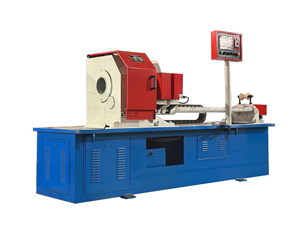
Steel pipe cutting is one of the earliest precision processes in conveyor roller manufacturing. Before a roller shell can enter end machining, bearing-seat assembly, welding, or inspection, the raw steel pipe must first be separated into consistent sections with controlled length and suitable end-face quality. Variation introduced during this stage can continue into every process that follows.
An automatic steel pipe cutting machine organizes feeding, positioning, clamping, and cutting into a repeatable production cycle. Instead of measuring and handling every section independently, the machine can move the pipe to a defined position, secure the workpiece, perform the cut, and prepare for the next cycle through coordinated mechanical and control systems.
For conveyor roller production, this is particularly useful because manufacturers often process repeated batches of round steel pipe within a defined diameter and wall-thickness range. Stable tube preparation provides a more predictable starting point for the specialized roller manufacturing machines used later in the process.
What Is an Automatic Steel Pipe Cutting Machine?
An automatic steel pipe cutting machine is specialized equipment that performs repeated steel pipe separation through controlled feeding, clamping, positioning, and cutting. Unlike manual cutting methods, the main stages are coordinated within a defined machine cycle, allowing multiple workpieces to be processed according to established settings.
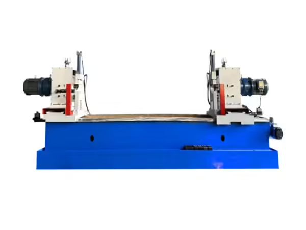
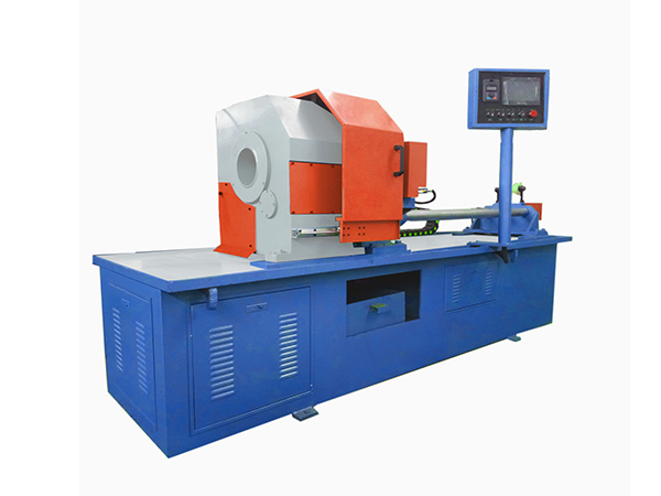
In the automatic steel pipe cutting process, the workpiece remains stationary while the cutting tool rotates. The pipe passes through the spindle and is positioned through a servo-driven feeding system before hydraulic clamping stabilizes it for cutting.
This arrangement is particularly suitable for round steel pipe used as conveyor roller shells because long raw material can remain aligned with the feeding direction rather than rotating as a complete workpiece. It also creates a clear relationship between material feeding, finished length, and the position of each cut.
Why Steel Pipe Cutting Matters in Roller Manufacturing
The roller shell establishes much of the external geometry of a conveyor roller. Although later operations influence bearing alignment, shaft position, welding, and rotational behavior, those processes all begin with a tube blank prepared during the cutting stage.
If the blank length varies from one workpiece to another, later machining may need to compensate for that difference. If the end face is uneven, the next operation may require additional material removal before a reliable reference surface can be established. Excessive burrs can also interfere with workpiece handling and subsequent processing.
For this reason, an automatic steel pipe cutting machine should not be evaluated only by whether it can separate material. The quality of the finished blank must also support the next stage of roller manufacturing.
A stable cutting process therefore focuses on length control, end-face condition, repeatability, workpiece support, and the consistency of every production cycle.
How the Automatic Cutting Cycle Works
A typical machine cycle begins when the raw steel pipe enters the feeding system. The servo-driven mechanism advances the workpiece according to the programmed length, after which the pipe is positioned and secured by the clamping system.
Once the workpiece is stable, the cutting mechanism begins its movement. In this machine structure, the pipe itself remains stationary while the cutting tool rotates. After the cut is completed, the tool retracts, the clamp releases, and the feeding system advances the next required section.
The process can then repeat without requiring the operator to measure every individual roller shell manually.
| Process Stage | Main Function | Effect on Roller Production |
|---|---|---|
| Feeding | Advances raw steel pipe | Establishes blank length |
| Positioning | Stops pipe at target location | Supports dimensional repeatability |
| Clamping | Stabilizes the workpiece | Prevents movement during cutting |
| Cutting | Separates roller shell blank | Creates required pipe section |
| Retraction | Resets cutting mechanism | Prepares the following cycle |
| Inspection | Confirms cut condition | Protects downstream machining quality |
The reliability of the complete cycle depends on all of these stages working together rather than on the cutting tool alone.
Why the Pipe Remains Stationary
Long round steel pipes can create additional handling challenges if the complete workpiece needs to rotate during cutting. Supporting a long rotating tube requires careful control of alignment, balance, and surrounding space.
A stationary-workpiece design avoids this issue by keeping the pipe aligned along the feeding direction while the cutting tool performs the rotational movement.
This structure is especially practical in conveyor roller production, where raw steel tubes may be supplied in long lengths and then divided into multiple roller shells. The feeding mechanism can move the pipe forward between cuts without changing the fundamental orientation of the material.
Keeping the pipe stationary also simplifies the relationship between the material supports, clamping point, and cutting location. When these elements remain correctly aligned, the machine can produce repeated sections using a more controlled mechanical reference.
Servo Feeding and Length Control
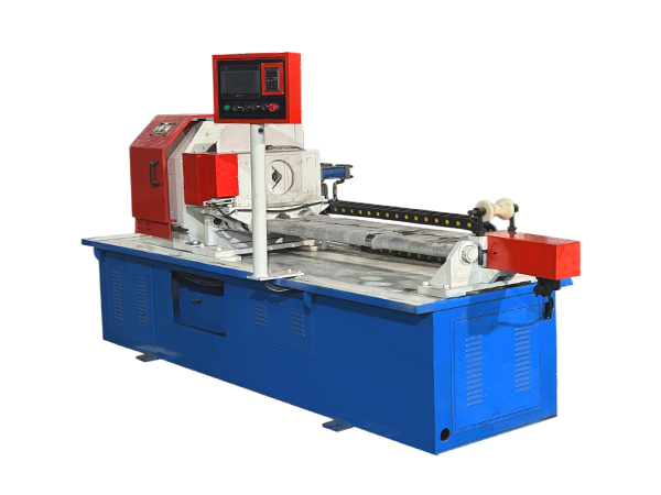
Accurate cutting begins before the tool contacts the steel. The feeding system determines where the pipe will stop, which directly influences the final blank length.
Servo control is useful because it allows the feeding movement to follow programmed position commands. Combined with ball screws and linear guides, the mechanism can repeatedly advance the material according to the required production setting.
A servo-controlled tube cutting system can integrate automatic length determination, feeding, and cutting within a PLC-controlled sequence. This reduces dependence on repeated manual measurement while giving operators a defined method for changing between roller specifications.
The first completed workpiece after a length adjustment should still be measured carefully. Automation improves repeatability, but inspection remains necessary to confirm that the programmed movement corresponds to the actual finished part.
Hydraulic Clamping and Workpiece Stability
The workpiece must remain stable after feeding and before cutting begins. If the steel pipe moves under cutting force, the finished length or end-face condition can change even when the feeding position was correct.
Hydraulic clamping provides a controlled method for securing the tube during the cutting stage. The clamp stabilizes the round workpiece while the rotating tool removes material.
For different pipe diameters, the clamping system must continue to hold the material along the intended machine centerline. Adjustment and maintenance therefore matter as much as the hydraulic pressure itself.
Clamping surfaces should also remain clean and in suitable condition. Wear, chips, or incorrect positioning can gradually change how the tube sits inside the machine and introduce variation into a process that otherwise uses identical control settings.
Cutting Round Steel Pipes for Roller Shells
Round steel pipe is widely used for conveyor roller shells because it provides the cylindrical structure required for continuous rotation. The cutting process needs to preserve this geometry while producing sections that correspond to the intended roller dimensions.
The machine should therefore be configured according to pipe diameter, wall thickness, raw stock length, finished section length, and material condition.
Diameter affects the way the pipe is supported and clamped, while wall thickness influences the amount of material removed during the cutting operation. Longer raw material also requires suitable feeding support so that the pipe remains aligned as successive sections are produced.
The finished roller shell should emerge from the cutting stage in a condition suitable for later machining rather than requiring extensive correction before the next operation begins.
Mechanical Pipe Cutting Compared With Thermal Methods
Industrial pipe cutting can use different methods depending on the required geometry, material, and subsequent fabrication process. Thermal processes are often associated with complex profiles, while mechanical cutting can be well suited to controlled straight separation when the production requirement is a repeatable tube blank.
For conveyor roller shells, the main requirement is normally a straight section of round steel pipe rather than a complex saddle, branch opening, or multi-axis profile.
A rotating mechanical cutting tool can therefore be appropriate when the process is designed around repeated straight cuts. Because the workpiece remains stationary, the machine does not need to rotate the complete length of steel pipe.
This distinction is important when evaluating equipment. An automatic steel pipe cutting machine should match the actual roller manufacturing task instead of introducing cutting technology intended for completely different pipe-processing applications.
End-Face Quality Affects the Next Operation
A finished cut creates the reference condition for later tube-end processing. If the face is significantly angled, rough, or inconsistent around the circumference, the next machine may need to remove additional material before the desired geometry can be established.
For conveyor roller manufacturing, consistent end faces make the transition into double-end machining more predictable. The tube can be loaded into the next process with a more stable starting length and less unnecessary variation between workpieces.
This does not mean that cutting must replace later precision machining. Instead, the cutting stage should produce a blank that allows the next machine to perform its intended operation efficiently and consistently.
The better these stages are coordinated, the easier it becomes to control the complete roller manufacturing workflow.
Burr Control in Steel Pipe Cutting
Burrs can develop around the cut edge as the tool separates the steel pipe. Their severity depends on tool condition, cutting parameters, material characteristics, clamping stability, and machine setup.
A small and predictable edge condition is generally easier to manage than irregular burr formation that changes from one workpiece to another.
Tool inspection is therefore an important part of the cutting process. As the cutting edge wears, the appearance and quality of the finished tube may gradually change. Monitoring the workpiece allows operators to recognize these changes before they become large enough to affect an entire production batch.
The objective should be to control burr formation during cutting rather than rely entirely on additional corrective work afterward.
Tool Condition and Cutting Consistency
The cutting tool directly interacts with the steel, so gradual wear can influence both process stability and surface condition.
A tool that has moved beyond its suitable working condition may create rougher edges, increased cutting resistance, or less predictable results. Because this change can develop gradually, operators may not immediately notice it without regular inspection.
Finished workpieces can provide useful feedback. Changes in cutting sound, burr condition, end-face appearance, or machine load can indicate that the tool or machine setup deserves closer attention.
For batch conveyor roller production, tool management should therefore form part of the production routine. Stable machine settings are most useful when the cutting tool itself also remains within a controlled operating condition.
Pipe Diameter and Wall Thickness
An automatic steel pipe cutting machine must be matched to the dimensions of the raw material being processed.
Pipe diameter influences clamping position, cutting-tool engagement, support configuration, and machine working range. Wall thickness changes the amount of steel that must be removed during each cycle and can affect cutting behavior.
Manufacturers should therefore evaluate diameter and wall thickness together rather than considering only the outside dimensions of the pipe.
The same principle applies when changing between roller specifications. Each new steel pipe size should be checked against the machine configuration before continuous production begins, and the first completed blanks should receive additional dimensional verification.
PLC Control and Repetitive Production
Automatic pipe cutting depends on several actions occurring in the correct sequence. Feeding should take place before clamping, the workpiece must be secured before the cutting cycle begins, and the tool should complete its movement before the next feeding operation starts.
PLC control coordinates these machine functions according to a defined operating sequence.
For repeated roller production, this allows the process to follow the same logic from one steel pipe blank to the next. The operator can establish production settings while the controller manages the timing and order of the machine actions.
However, a PLC cannot correct mechanical problems automatically. Tool condition, guide accuracy, clamping alignment, material straightness, and machine maintenance still influence the final workpiece.
Control technology is therefore most effective when it works together with a stable mechanical process.
Connecting Pipe Cutting With Double-End Tube Machining
After the steel pipe has been cut into roller shell blanks, the workpiece may require further machining at both ends.
The cutting stage establishes the approximate final shell length, while later machining creates the geometry required for bearing housing installation or related roller components.
This relationship makes tube cutting and double-end machining closely connected. If the cutting process produces widely varying blanks, the following machine receives workpieces with inconsistent starting conditions.
A well-controlled automatic steel pipe cutting machine reduces this variation and provides a more predictable supply of tube blanks for the next production stage.
Production planning should therefore evaluate the two operations together rather than maximizing the output of the cutting machine without considering downstream capacity.
Quality Checks After Cutting
Inspection after cutting should confirm that the blank is ready for the next manufacturing stage.
Finished length is one of the most important measurements, but end-face condition, visible deformation, burr level, and consistency between multiple blanks should also be observed.
The first workpiece after a machine adjustment deserves particular attention because it confirms whether the new settings produce the intended result. During longer production runs, periodic measurements can show whether the process remains stable over time.
Inspection data can also help identify the source of variation. If length changes while cut appearance remains consistent, the feeding system may require attention. If length remains stable but burrs increase, tool condition may be the more likely cause.
Common Causes of Inconsistent Steel Pipe Cuts
Cutting variation often develops from several interacting factors rather than one obvious machine fault.
Raw steel pipe may vary in straightness or wall condition. Feeding components can lose accuracy if guide systems are not maintained. Clamping surfaces may wear, while cutting tools gradually lose their original edge condition.
Machine troubleshooting should therefore follow the actual production sequence. Raw material should be checked first, followed by feeding position, workpiece clamping, cutting-tool condition, mechanical movement, and finished-part measurement.
This approach avoids changing several machine settings at once and makes it easier to identify where variation first entered the process.
Maintaining an Automatic Steel Pipe Cutting Machine
Routine maintenance supports both machine reliability and finished-part consistency.
The feeding mechanism, ball screw, linear guides, hydraulic clamping system, cutting spindle, servo components, sensors, and control system should be inspected according to the machine’s operating requirements.
Chips and cutting debris should also be removed regularly from areas where they can interfere with material support, guides, or moving components.
Maintenance should be connected with production observations. Changes in sound, vibration, movement, cutting surface, or dimensional results may provide early indications that inspection is needed.
A stable maintenance routine helps ensure that the cutting conditions established during machine setup continue to produce similar results across later production batches.
Selecting the Right Machine Configuration
The machine configuration should begin with the steel pipe and roller specifications.
Manufacturers need to define the pipe diameter, wall thickness, material, raw stock length, finished roller shell length, expected batch structure, and downstream machining process.
Working range is only one consideration. Feeding accuracy, clamping method, tool configuration, automation, adjustment between specifications, inspection requirements, and integration with later roller-processing equipment should also be evaluated.
The most suitable automatic steel pipe cutting machine is therefore not simply the machine with the fastest individual cutting cycle. It is the machine that produces consistent blanks and fits naturally into the complete conveyor roller production process.
Building a Stable Roller Tube Preparation Process
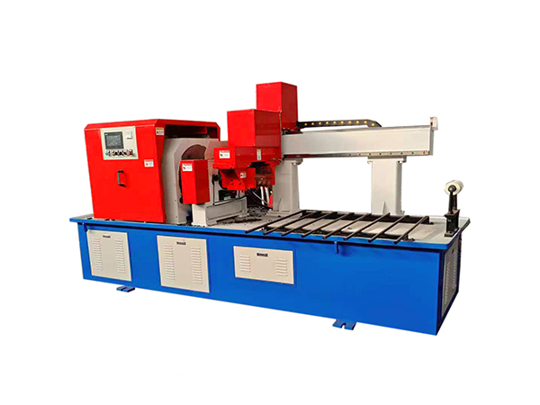
A reliable tube preparation process begins before material reaches the cutting tool.
Raw steel pipe should meet the intended dimensional requirements, feeding should remain controlled, workpiece clamping should establish a stable position, and the cutting mechanism should operate with suitable tooling.
After cutting, inspection confirms whether the workpiece is ready for the next operation. Measurement results then provide feedback that can be used to monitor feeding accuracy, tooling condition, and machine stability.
When these steps are treated as one connected process, automatic steel pipe cutting becomes more than material separation. It becomes the first controlled machining stage in conveyor roller production.
Conclusion
An automatic steel pipe cutting machine provides a structured method for preparing round steel pipe used in conveyor roller manufacturing. By coordinating servo feeding, hydraulic clamping, PLC control, and rotating-tool cutting, the machine can repeatedly produce tube blanks while the long workpiece remains stationary.
Reliable results depend on more than automation. Raw material dimensions, workpiece support, tool condition, feeding accuracy, clamping stability, end-face quality, inspection, and machine maintenance all influence the finished roller shell.
The cutting stage should also be coordinated with the double-end machining and assembly operations that follow. When steel pipe blanks enter those stages with consistent length and edge condition, the complete roller manufacturing process becomes easier to control.
For this reason, automatic steel pipe cutting should be treated as an integrated part of roller production rather than an isolated cutting operation.
FAQ
What is an automatic steel pipe cutting machine used for?
An automatic steel pipe cutting machine prepares repeated round steel pipe sections through controlled feeding, positioning, clamping, and cutting. In conveyor roller production, these sections become roller shell blanks that later move into tube-end machining, assembly, welding, and inspection processes.
Why does the steel pipe remain stationary during cutting?
Keeping the pipe stationary allows long raw material to remain aligned with the feeding direction while the cutting tool rotates. This reduces the need to rotate the complete workpiece and creates a stable relationship between the pipe support, clamping position, feed movement, and cutting location.
How does servo feeding improve cutting repeatability?
Servo feeding controls material movement according to programmed position commands, helping each pipe section advance by a defined distance before cutting. Ball screws and linear guides support this movement mechanically, while dimensional inspection confirms that programmed positions continue to match the finished blanks.
What should be checked after cutting a steel pipe blank?
Inspection should include finished length, end-face condition, visible deformation, burr level, and consistency between repeated sections. The first workpiece after a setup change should receive closer dimensional verification before the machine continues with a longer production batch.
Why is pipe cutting important before roller end machining?
Pipe cutting establishes the starting dimensions of the roller shell before more precise end processing begins. Consistent blanks give double-end machining equipment a more predictable workpiece, while large variations in length or face condition can create additional material removal and setup differences later.
 English
 French
 Spanish