

Table of Contents
Introduction
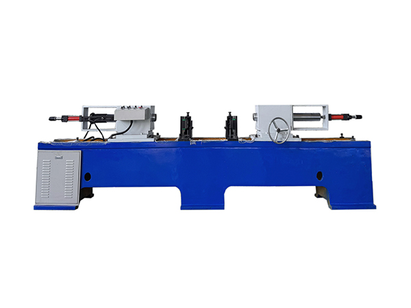
Bearing assembly is one of the most important stages in conveyor roller production because the relationship between the shaft, bearing, bearing housing, and roller tube directly affects how the completed roller is assembled. Even when upstream machining is accurate, inconsistent pressing can introduce variation during the final assembly stage.
An automatic press machine helps organize this process by replacing repeated manual force application with a controlled hydraulic pressing cycle. For conveyor roller production, a double-end structure is particularly suitable because bearing-related components are normally installed at both ends of the roller. Processing both sides within one machine setup reduces unnecessary repositioning and creates a more consistent assembly sequence.
The objective is not simply to apply greater force. Reliable pressing depends on workpiece alignment, roller dimensions, hydraulic stability, component tolerances, spindle coaxiality, fixture condition, and correct operating procedures. This guide explains how an automatic press machine works in conveyor roller production and which technical factors matter most during batch assembly.
What Is an Automatic Press Machine?
An automatic press machine uses a controlled mechanical or hydraulic system to apply force to a workpiece during assembly, forming, fitting, or other production operations. In roller manufacturing, the pressing function is commonly used to install bearing-related components at both ends of a prepared roller assembly.
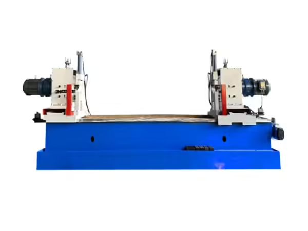
The double-end hydraulic bearing-setting process used for conveyor rollers combines manual workpiece loading with automatic hydraulic press-fitting. The two pressing heads operate from opposite directions so that both sides can be processed within the same machine structure.
This equipment is more specialized than a general workshop press because the machine is designed around long cylindrical roller assemblies. Its working range, spindle position, supports, hydraulic system, and control sequence are configured specifically for repeated conveyor roller production.
Why Hydraulic Pressing Is Suitable for Roller Assembly
A hydraulic press uses hydraulic cylinders to generate compressive force. In manufacturing, this principle is widely used where controlled linear force is required for fitting or assembly operations.
For conveyor roller production, hydraulic pressing provides a stable method of moving the pressing heads toward the bearing assemblies. Instead of using impact or inconsistent manual force, the machine performs the movement through a defined hydraulic system.
The advantage is not simply force capacity. Hydraulic movement can be coordinated with machine positioning, workpiece support, and PLC control so that each production cycle follows the same basic sequence.
This makes the technology suitable for repetitive roller assembly where manufacturers need to process many components with similar geometry while maintaining controlled conditions.
How an Automatic Press Machine Works
The assembly process begins when the prepared conveyor roller is placed in the working position. The roller is supported so that its centerline corresponds with the two pressing spindles located at opposite ends of the machine.
Once the workpiece has been positioned correctly, the hydraulic system moves the pressing heads toward the roller. Both sides can operate simultaneously, allowing the bearing-related components at each end to be fitted within the same cycle.
After the required pressing position has been reached, the hydraulic system retracts the pressing heads. The assembled roller can then be removed and transferred to inspection or another production stage.
| Process Stage | Main Function | Production Purpose |
|---|---|---|
| Workpiece loading | Place roller in machine | Prepare assembly |
| Positioning | Align roller centerline | Establish pressing axis |
| Support | Stabilize long workpiece | Prevent movement |
| Hydraulic pressing | Move both pressing heads | Install components |
| Position completion | Reach required fit | Complete assembly |
| Retraction | Return pressing heads | Prepare unloading |
| Inspection | Check assembly condition | Confirm consistency |
Although the sequence is relatively simple, every stage affects the final assembly result.
Why Double-End Pressing Is Important
A conveyor roller normally contains corresponding bearing assemblies at both ends. If each end is processed separately, the workpiece must either be reversed or transferred between two independent pressing operations.
Each additional setup creates another opportunity for positioning variation.
A double-end automatic press machine allows the complete roller to remain in one machine position while two pressing spindles act from opposite directions. The relationship between the two operations is therefore established by the same machine structure.
This approach can reduce workpiece handling and make the assembly process easier to repeat during batch manufacturing.
The effectiveness of double-end pressing still depends on correct machine alignment and component preparation. Simultaneous movement cannot compensate for bearing housings, shafts, or roller tubes that do not match the intended dimensions.
Spindle Coaxiality and Assembly Accuracy
Pressing force needs to follow the intended roller axis. If the two pressing spindles are poorly aligned, force may act unevenly on the components being installed.
This is why spindle coaxiality is an important technical parameter for a double-end automatic press machine.
For the TY-220×2200 model currently listed on the product page, the coaxial deviation between both pressing spindles is specified at no more than 0.1 mm. The machine center height is 850 mm, creating a defined mechanical reference for roller positioning.
These specifications show that roller pressing equipment should not be evaluated only according to force. Geometry and alignment are equally important because they determine how that force reaches the workpiece.
During production, fixture wear and workpiece positioning should also be monitored so that the roller remains aligned with the machine centerline.
Matching the Machine to Roller Diameter
Roller diameter affects how the workpiece is supported, positioned, and aligned between the pressing heads.
The TY-220×2200 configuration supports roller diameters from Φ76 to Φ219 mm. This range covers several commonly manufactured conveyor roller sizes, but manufacturers should always compare the actual product drawings with the machine’s working limits.
Changing roller diameter may require adjustment of workpiece supports or other positioning components. The machine should continue to hold the roller on the correct centerline after each specification change.
The first assembly after an adjustment should therefore receive additional inspection before the remaining batch is processed.
This is particularly important in factories where several roller diameters are manufactured using the same automatic press machine.
Roller Length and Pressing Head Adjustment
Conveyor rollers can vary significantly in length depending on belt width, conveyor structure, and application requirements.
The current machine specification covers roller lengths from 200 to 2200 mm. This broad working range means that the relative position of the two pressing areas must be adjustable for different workpieces.
Longer rollers also require suitable intermediate support. Without proper support, the workpiece can sag or become misaligned relative to the pressing spindles.
Machine adjustment should therefore consider both overall roller length and the exact location where pressing force needs to be applied.
For repeated production, validated setup positions can help operators move between specifications more consistently instead of establishing every machine adjustment from the beginning.
Understanding Maximum Pressing Force
The listed maximum pressing force for the TY-220×2200 model is 4000 kgf, while hydraulic system working pressure is specified at 2.5–4.5 MPa.
These figures describe the capability of the hydraulic system, but maximum force should not be treated as the normal target for every assembly.
The required pressing condition depends on component dimensions, fit, bearing housing structure, material, and the intended final position. Applying unnecessary force does not correct dimensional errors in the components.
A stable pressing process begins with correctly manufactured parts. Hydraulic force should then be used to complete the intended assembly under controlled conditions.
This is why dimensional inspection before pressing is an important part of the production process.
Bearing Housing Structure Affects the Pressing Process
Conveyor rollers may use different bearing housing structures. The current equipment is designed for rollers using cast iron or pressed bearing housings, which means the pressing arrangement must accommodate more than one component configuration.
The housing geometry influences where the pressing tool contacts the assembly and how force is transferred toward the bearing position.
Fixtures and pressing surfaces should therefore match the actual roller design. A machine working successfully with one housing configuration may require adjustment before another structure is processed.
Manufacturers should review bearing housing dimensions, shaft geometry, bearing position, sealing components, and retaining features before establishing the machine setup.
The automatic press machine then becomes part of a controlled assembly process rather than a general force-producing device.
Why Component Tolerances Matter
Press fitting depends on the relationship between mating components. If the shaft, bearing housing, or related surfaces vary outside their intended dimensional limits, the required pressing behavior can also change.
One roller may assemble smoothly while another requires noticeably different force even though both are processed using identical machine settings.
This variation may originate upstream rather than inside the pressing machine.
For this reason, important component dimensions should be inspected before assembly. Tube-end machining, shaft machining, bearing housing dimensions, and bearing selection all influence the pressing stage.
The strongest automatic press machine process begins with predictable components and uses controlled hydraulic movement to assemble them consistently.
PLC Control in Automatic Pressing
The PLC coordinates the operating sequence of the machine. Once the workpiece has been loaded and correctly positioned, the controller can manage hydraulic movement, pressing completion, return motion, and related machine functions.
This makes the sequence easier to repeat across a production batch.
However, PLC control does not measure every mechanical variable automatically. If the roller is loaded incorrectly or the fixture has moved, the controller may still execute the same programmed sequence.
Production stability therefore requires both control-system repeatability and mechanical process discipline.
Operators should combine correct setup procedures with routine checks of pressing surfaces, spindle alignment, hydraulic condition, fixtures, sensors, and finished assemblies.
Semi-Automatic Operation in Batch Production
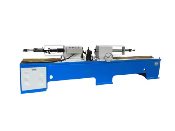
Although the equipment uses automatic pressing functions, workpiece loading is manual. This creates a semi-automatic production structure that can be practical when manufacturers process multiple roller specifications.
Manual loading gives operators flexibility when changing between roller dimensions, while hydraulic double-end pressing standardizes the critical force-application stage.
For batch production, this balance can reduce repetitive manual work without requiring a completely automated transfer system.
The operator remains responsible for confirming workpiece position before the pressing cycle begins. Clear loading and positioning procedures are therefore important.
When operators follow the same sequence and the machine remains correctly adjusted, semi-automatic pressing can provide a stable workflow across repeated roller assemblies.
How Pressing Fits Into the Roller Manufacturing Process
Bearing pressing does not occur in isolation. Before the workpiece reaches the press, the roller tube and shaft need to pass through several machining stages.
Tube cutting establishes the shell blank. Double-end tube machining prepares the ends for later components, while shaft milling, grooving, or other processes create the geometry needed for assembly.
These roller manufacturing processes need to supply components with sufficiently stable dimensions before the automatic press machine performs bearing setting.
After pressing, the roller may proceed to welding, sealing, rotational inspection, or other finishing operations depending on its construction.
This means production quality should be analyzed across the complete manufacturing chain rather than only at the pressing station.
Upstream Machining Directly Affects Pressing
A press machine cannot compensate reliably for incorrectly machined components.
If the roller tube ends differ between workpieces, bearing housings may not reach the same position during assembly. If shaft dimensions vary, the bearing fit can behave differently. Poor component alignment can also change the direction in which pressing force is transferred.
These problems illustrate why upstream machining needs its own dimensional control.
When tube, shaft, bearing housing, and bearing dimensions remain predictable, pressing becomes much easier to standardize.
If abnormal resistance appears during assembly, operators should investigate the incoming components before simply increasing hydraulic settings. This reduces the risk of using the press to hide dimensional problems created earlier in production.
Workpiece Support for Long Rollers
Supporting a long cylindrical workpiece correctly is an important part of pressing alignment.
A roller extending beyond one meter can experience noticeable sag if support positions are inappropriate. Even small changes in workpiece position can affect its relationship with the pressing spindles.
Supports should therefore hold the roller close to its intended centerline without interfering with the movement of the pressing heads.
When roller length changes, support positions may also need adjustment.
Routine production procedures should define how the workpiece is placed and supported for each common specification. This helps ensure that different operators establish similar starting conditions before pressing begins.
Common Causes of Inconsistent Pressing
Variation during roller bearing assembly can originate from several different sources.
Component tolerances are one possibility. Incorrectly machined shafts, housings, or tube ends may require different pressing conditions. Workpiece positioning is another common factor because a roller that is not aligned correctly may experience uneven loading.
Fixture wear, spindle alignment, hydraulic performance, and contamination on pressing surfaces can also influence results.
Troubleshooting should therefore follow a structured sequence. Manufacturers should first verify the incoming components, then check workpiece positioning and supports, followed by pressing surfaces, machine alignment, hydraulic condition, and finished assembly.
Changing hydraulic settings without identifying the source of variation can make the process more difficult to control.
Quality Inspection After Pressing
The assembly should be checked before the roller moves further through production.
Inspection may include bearing position, symmetry between both ends, shaft relationship, visible component condition, and roller rotation. The exact inspection points depend on the roller design and manufacturing requirements.
For double-end pressing, comparing the two sides of the same roller is particularly useful. If one end repeatedly differs from the other, the problem may relate to spindle position, tooling, fixture adjustment, or incoming component dimensions.
Inspection records can also reveal gradual process changes across a production batch.
This makes quality inspection useful not only for evaluating finished rollers but also for monitoring machine condition.
Maintenance of the Hydraulic System
Stable hydraulic movement depends on the condition of the hydraulic unit, cylinders, seals, valves, lines, and fluid.
Leakage or irregular pressure can change the way the pressing heads move. Hydraulic contamination can also affect system reliability over time.
Maintenance should therefore follow the machine’s operating requirements and include routine observation of pressure behavior, movement, leakage, and fluid condition.
Operators should also monitor whether the two pressing sides continue to move consistently during repeated production.
Hydraulic maintenance is directly connected with process control because changes in machine movement can eventually appear as changes in the finished roller assembly.
Inspecting Pressing Spindles and Fixtures
The pressing spindles and workpiece fixtures create the mechanical relationship between the machine and the roller.
Contact surfaces should remain clean and free from damage. Fixtures should continue locating the roller at the correct center height, while pressing spindles should maintain the intended alignment.
Wear develops gradually, so periodic inspection is more effective than waiting for an obvious assembly defect.
When several roller specifications are processed, adjustment mechanisms should also be checked to confirm that repeated changes have not introduced looseness or positioning errors.
Maintaining these components supports the repeatability of the automatic press machine over longer production periods.
Balancing Press Capacity With Production Flow
The performance of one machine should be considered in relation to the rest of the production line.
If tube machining and shaft preparation cannot supply workpieces at the same general production rhythm, increasing pressing speed alone may not improve overall output.
Similarly, if welding or inspection after pressing becomes a bottleneck, assembled rollers may accumulate between stages.
Manufacturers should therefore evaluate production as a connected flow. Cycle time, specification changes, workpiece handling, inspection, and transfer between machines all influence real production performance.
An automatic press machine provides the greatest value when its operating rhythm matches the processes around it.
When an Automatic Press Machine Is Most Useful
This equipment is especially suitable for repeated conveyor roller assembly where similar bearing-related components need to be installed at both ends.
Batch production benefits from the ability to maintain one machine structure, one centerline, and one controlled hydraulic sequence across many workpieces.
Factories producing several roller specifications can also use adjustable working ranges to process different diameters and lengths, provided the workpieces fall within the intended machine capability.
The equipment is less about replacing every manual activity and more about standardizing the assembly operation that requires controlled axial force.
This distinction is important when planning realistic automation for roller production.
How to Evaluate an Automatic Press Machine
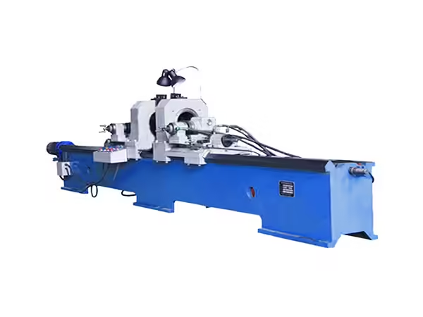
Machine evaluation should begin with the roller drawing rather than with general equipment specifications.
Important factors include roller diameter, overall length, shaft arrangement, bearing housing structure, bearing position, required pressing distance, and component tolerances.
The machine’s working range, spindle coaxiality, hydraulic pressure, maximum pressing capability, fixture adjustment, PLC control, support structure, and maintenance access should then be compared with these requirements.
Manufacturers should also examine upstream and downstream processes. A press machine performs best when incoming components are already dimensionally controlled and the completed roller can move efficiently into the next production stage.
Conclusion
An automatic press machine provides a controlled method for installing bearing-related components during conveyor roller assembly. Double-end hydraulic pressing is particularly suitable for this application because corresponding components at both ends can be processed within one machine setup.
Reliable results depend on more than hydraulic force. Spindle coaxiality, roller diameter, roller length, bearing housing structure, workpiece support, incoming component tolerances, PLC control, fixtures, and maintenance all influence assembly consistency.
The pressing process should also be connected with tube machining, shaft preparation, welding, and inspection. When upstream components are predictable and the machine is correctly configured, automatic pressing becomes a stable and repeatable stage within the complete conveyor roller manufacturing workflow.
FAQ
What is an automatic press machine used for in conveyor roller production?
An automatic press machine uses controlled hydraulic movement to install bearing-related components at both ends of a conveyor roller. The workpiece is positioned along a defined centerline, while opposing pressing heads perform the fitting operation within one coordinated production cycle.
Why is double-end pressing useful for conveyor rollers?
Conveyor rollers normally contain corresponding bearing assemblies at both ends. Double-end pressing allows both sides to be processed while the roller remains in one machine position, reducing repeated handling and helping maintain a more consistent relationship between the two assembled ends.
What roller sizes can the TY-220×2200 machine process?
The listed working range covers roller diameters from Φ76 to Φ219 mm and lengths from 200 to 2200 mm. Machine setup must also consider bearing housing geometry, shaft design, pressing position, workpiece support, and the dimensional condition of incoming components.
Why is spindle coaxiality important during hydraulic pressing?
The two pressing heads need to act along a controlled axis so force reaches both ends of the roller consistently. Excessive misalignment can affect component positioning. The TY-220×2200 specification lists coaxial deviation between the two pressing spindles at no more than 0.1 mm.
What should be checked after roller bearing pressing?
Inspection should verify bearing position, symmetry between both ends, visible component condition, shaft relationship, and roller rotation where applicable. Repeated differences between the two sides may indicate issues with fixtures, spindle alignment, component dimensions, or workpiece positioning.
 English
 French
 Spanish