

Table of Contents
Introduction
Selecting industrial pipe-cutting equipment requires more than comparing maximum pipe diameter or machine power. For conveyor roller manufacturing, the cutting machine is responsible for creating the first controlled tube blank before the workpiece enters end machining, bearing assembly, welding, and final inspection. Any instability introduced at this stage can continue through the rest of the manufacturing process.
A pipe cutting machine manufacturer therefore needs to demonstrate more than basic cutting capability. The equipment should match the actual steel pipe range, maintain repeatable feeding and clamping, provide a stable relationship between the workpiece and cutting tool, and integrate naturally with downstream roller production. Machine rigidity, control logic, tooling, maintenance accessibility, and technical understanding of the complete production process all influence long-term machining consistency.
The following seven checks provide a practical framework for evaluating a pipe cutting machine manufacturer for repetitive round steel pipe processing and conveyor roller production.
Check 1: Does the Machine Match the Actual Steel Pipe?
Machine evaluation should begin with the workpiece rather than with the equipment specification sheet. Outside diameter, wall thickness, raw stock length, finished blank length, material type, and production batch size determine the cutting conditions the machine needs to handle.
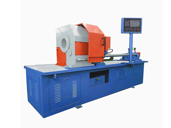
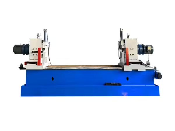
The existing automatic pipe cutting machine is specifically designed to feed, clamp, and cut round steel pipes. Its QZ160 configuration covers approximately Φ60–159 mm pipe diameter and 3–8 mm wall thickness, providing a defined working range for medium-thickness steel tube processing.
These two dimensions need to be considered together because two pipes with the same outside diameter can behave differently when wall thickness changes. A manufacturer should therefore evaluate the complete material envelope instead of recommending equipment according to one maximum diameter alone.
Why Working Range Should Reflect Real Production
Selecting a machine with a very broad theoretical range provides little benefit if most production falls within a much narrower group of dimensions. What matters is whether the equipment can repeatedly process the roller tubes that are actually manufactured.
A factory producing several roller families should map its common pipe diameters, wall thicknesses, and blank lengths before machine selection begins. This allows the working range to be evaluated against real production rather than occasional extreme specifications.
The same information also helps determine tooling requirements, material support, feeding length, clamping arrangement, and the frequency of production changeovers.
Check 2: How Is the Steel Pipe Fed and Positioned?
Length accuracy begins before cutting. If the raw pipe does not stop at a repeatable position, even a stable cutting spindle cannot produce consistent blanks.
The QZ160 uses a servo motor combined with a ball screw for material feeding. This structure converts programmed movement into controlled longitudinal pipe travel before each cutting cycle. Its listed single feeding range is approximately 20–1200 mm.
For repeated conveyor roller production, servo-controlled feeding reduces dependence on manual measurement and repositioning. Once the target blank length is established, the system can reproduce the same basic feeding sequence across multiple workpieces.
A pipe cutting machine manufacturer should therefore explain not only that the equipment feeds automatically, but also how the mechanical transmission, servo system, guides, and control logic work together to maintain positioning consistency.
Feeding Accuracy Depends on Mechanical Condition
Servo control alone does not guarantee dimensional stability. Ball-screw wear, guide contamination, loose connections, unsuitable material support, or pipe movement during clamping can all influence the finished blank even when the programmed feed distance remains unchanged.
For this reason, machine design should allow important feeding components to be inspected and maintained without excessive disassembly. Operators should also be able to recognize gradual changes in feeding behavior through dimensional checks of finished tube blanks.
This connection between the control system and mechanical condition is an important indicator of whether the machine has been designed for sustained industrial production rather than short demonstrations.
Check 3: How Is the Pipe Clamped During Cutting?
After the steel pipe reaches the programmed position, it needs to remain stable until the cutting tool has completely separated the blank.
The current machine uses self-centering hydraulic clamping. For round pipe, this helps establish a stable relationship between the cylindrical workpiece and cutting center while reducing unwanted movement during tool engagement.
Clamping is particularly important because the tube remains stationary during the actual cutting operation. The system therefore needs to resist cutting forces without allowing the workpiece to move longitudinally or change its position relative to the rotating cutter.
A manufacturer should consider how the clamp adapts to different pipe diameters, how clamping surfaces are maintained, and how operators verify that the workpiece remains centered after a specification change.
Why Self-Centering Matters for Round Pipe
A round tube requires a reliable center reference. If the pipe sits differently in the clamp from one cycle to another, the cutting tool can encounter inconsistent geometry even when every control parameter remains unchanged.
Self-centering clamping helps reduce this variation by positioning the round workpiece more consistently within the machine structure. However, the effectiveness of the system still depends on clean contact surfaces, correct hydraulic operation, and suitable adjustment for the actual pipe diameter.
The first workpiece after changing specifications should therefore be inspected carefully so the new clamping condition can be confirmed before continuous processing begins.
Check 4: Does the Machine Use the Right Cutting Structure?
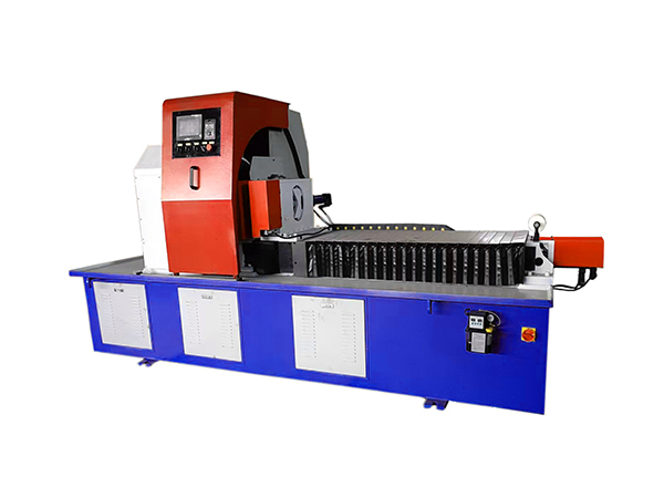
One of the defining features of this pipe-cutting system is its stationary-workpiece and rotating-tool design. The steel pipe performs only longitudinal feeding movement, while the cutter holder rotates around the tube during cutting.
This arrangement is particularly suitable for long round steel stock because the complete pipe does not need to rotate at cutting speed. Long material can remain supported along the machine axis, simplifying the mechanical behavior of the raw stock while the cutting action remains concentrated around the cutting position.
For conveyor roller production, where the required operation is normally a straight transverse cut, this mechanical structure provides a logical manufacturing solution without introducing processes intended for complex pipe profiles.
Why Long Pipe Handling Matters
Raw steel tube can extend several meters beyond the cutting position, so material handling needs to be considered as part of machine design. Poor support can allow the tube to sag, shift sideways, or enter the spindle at an inconsistent angle.
A technically capable pipe cutting machine manufacturer should therefore consider the relationship between feeding racks, machine centerline, clamping position, and raw material length. The accuracy of the machine itself can only be maintained when the workpiece reaches it under controlled conditions.
Stable material support also becomes more important as production moves from occasional cutting to continuous processing of multiple roller shell blanks.
Check 5: Can the Machine Produce a Suitable End Face?
Cutting quality should be evaluated according to what happens next in production. A roller shell blank normally proceeds into additional tube-end machining, so the cutting operation should create a workpiece that provides a stable starting condition for that process.
Large burrs, excessive angular variation, or deformation around the pipe end can create additional material removal during downstream machining. Even when finished length is acceptable, poor end-face quality can reduce the predictability of the next manufacturing stage.
The QZ160 can use white steel or carbide cutting tools depending on the processing condition. Tool selection and tool wear therefore need to be considered together with pipe diameter, wall thickness, spindle speed, and feed behavior.
Tool Condition Is Part of Process Control
A cutting tool gradually changes as it processes steel. The edge can wear, cutting resistance can increase, and the finished surface may begin to show more burr formation or irregularity.
A good machine design should make tool inspection and replacement straightforward enough that operators can maintain a defined cutting condition. Waiting until the tool produces severe deterioration across an entire batch makes downstream production more difficult.
Finished workpieces can also serve as a useful diagnostic signal. Changes in end-face appearance, burr formation, cutting sound, or machine load can indicate that tooling or spindle condition deserves attention.
Check 6: Does the Control System Support Repetitive Production?
Automatic pipe cutting involves several operations that need to occur in the correct sequence. The tube must feed to position, the clamp must secure the workpiece, the cutting system must complete its movement, the tool must retract, and the next feeding cycle must begin only after the machine has returned to the correct condition.
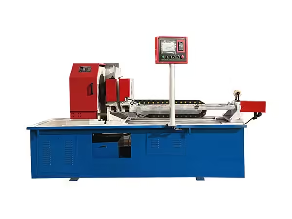
PLC-based control coordinates these actions and reduces dependence on repeated manual commands. The QZ160 also uses frequency-conversion stepless spindle-speed regulation, allowing rotational conditions to be adjusted for different steel pipe specifications.
For repetitive roller production, this combination supports a more standardized process. Operators still need to establish suitable machining parameters, but once a configuration has been verified, the machine can reproduce the same operating sequence throughout the batch.
Automation Should Not Replace Inspection
Automatic control improves repeatability, but it does not eliminate the influence of raw material variation, tool wear, hydraulic condition, or mechanical alignment.
The first tube after a machine adjustment should therefore be measured before continuous production begins. During longer batches, periodic inspection can confirm that the process remains stable rather than assuming that an unchanged PLC program always produces an unchanged physical result.
A technically responsible pipe cutting machine manufacturer should therefore treat automation and quality control as complementary parts of the same process.
Check 7: Does the Machine Fit the Complete Roller Manufacturing Process?
Pipe cutting is only one stage in conveyor roller manufacturing. After the tube blank has been produced, its ends may require additional machining before bearing housings, bearings, shafts, seals, and welded components are assembled.
The wider conveyor roller manufacturing machinery includes dedicated equipment for automatic tube cutting, double-end tube machining, roller shaft flat milling, circlip grooving, shaft-end preparation, bearing setting, and double-end welding. These stages show why cutting equipment should be evaluated as part of a connected manufacturing route rather than as an isolated machine.
When the cutting process delivers predictable blanks, the next machine receives a more consistent starting workpiece. This reduces the need for downstream processes to compensate for variation created during raw material preparation.
Connecting Cutting With Double-End Tube Machining
The Automatic Roller Double End Holes Lathe is designed specifically to process the ends of steel pipe used in belt conveyor rollers. This creates a direct technical relationship between the cutting stage and the following end-machining stage.
The pipe cutting machine establishes blank length and initial end condition, while the double-end lathe creates the more precise geometry required for later roller components. If the blank length varies significantly, the lathe must work with a different starting condition on every workpiece.
A manufacturer familiar with roller production should understand this relationship. Machine capability should be judged partly by how well the finished tube supports downstream machining rather than only by how quickly the cut itself is completed.
Machine Rigidity and Spindle Stability
The cutting tool repeatedly engages steel while rotating around a stationary workpiece. Machine rigidity therefore influences vibration, cutting behavior, and end-face consistency.
The spindle, tool holder, machine frame, clamping system, and feeding structure need to maintain their relative positions while cutting forces are applied. Excessive mechanical movement can reduce the benefit of an accurate servo feeding system.
A pipe cutting machine manufacturer should therefore consider structural stability throughout the machine rather than concentrate only on control-system specifications.
Changes in vibration or cutting sound during operation should be treated as maintenance signals because they may indicate gradual changes in tooling, spindle condition, fastening, or workpiece support.
Evaluating Spindle Speed Control
Different steel pipe dimensions can require different machining conditions. A fixed spindle speed may not provide the flexibility needed when diameter, wall thickness, tool material, or workpiece condition changes.
Frequency-conversion stepless speed regulation allows rotational speed to be adjusted according to the established cutting process. This does not mean that higher speed always produces better results. Cutting conditions need to balance spindle rotation, tool feed, wall thickness, pipe material, and tool condition.
The manufacturer should therefore provide a machine structure that allows parameters to be adjusted while keeping the process predictable across different roller tube specifications.
Technical Parameters Should Be Read as a System
Machine specifications are most useful when they are evaluated together rather than independently.
| Technical Item | QZ160 Reference | Why It Matters |
|---|---|---|
| Pipe diameter | Φ60–159 mm | Defines tube range |
| Wall thickness | 3–8 mm | Defines cutting load range |
| Main motor | 5.5 kW | Supports spindle cutting |
| Workpiece movement | Stationary | Simplifies long-tube cutting |
| Cutter movement | Rotating | Creates transverse mechanical cut |
| Clamping | Hydraulic self-centering | Stabilizes round pipe |
| Feeding | Servo motor + ball screw | Controls blank positioning |
| Single feed | 20–1200 mm | Defines feed-length capability |
| Spindle speed | Variable-frequency regulation | Supports parameter adjustment |
| Tool options | White steel / carbide | Supports different cutting conditions |
No single value determines whether the machine is suitable. The complete specification needs to match the tube families being manufactured.
First-Piece Inspection Should Be Part of Setup
When pipe diameter, wall thickness, finished blank length, cutting tool, or spindle condition changes, the first completed workpiece should receive additional inspection.
Finished length should be measured, while end-face quality, burr formation, visible deformation, and workpiece condition should also be evaluated. This confirms whether the programmed setup produces the intended physical result.
If the first piece does not meet the required condition, the source of variation can be investigated before the same setup is repeated across a larger production batch.
This simple process provides an important connection between machine adjustment and real manufacturing quality.
How to Diagnose Cutting-Length Variation
If finished tube lengths begin changing during production, troubleshooting should follow the sequence in which the workpiece moves through the machine.
Raw material support should be inspected first because misaligned long stock can affect feeding behavior. The servo motor, ball screw, guides, and associated transmission should then be checked for movement or wear. Hydraulic clamping should also be verified to ensure that the tube does not shift after positioning.
Only after these mechanical factors have been reviewed should control parameters be changed. This structured approach helps avoid adjusting software values to compensate for a physical problem elsewhere in the machine.
How to Diagnose Increasing Burr Formation
Burr formation is more closely related to cutting conditions than to length positioning. If the blank remains dimensionally consistent while edge quality deteriorates, the cutting tool should be one of the first components inspected.
Tool wear, unsuitable spindle conditions, workpiece vibration, clamping instability, or material variation can all influence the finished edge. Comparing several consecutive workpieces can help determine whether the change developed gradually or appeared immediately after a setup adjustment.
A pipe cutting machine manufacturer should design the equipment so these major process elements can be inspected logically rather than requiring extensive disassembly for routine troubleshooting.
Maintenance Accessibility Matters
Industrial production equipment needs regular cleaning, lubrication, tooling changes, hydraulic inspection, and mechanical checks. A machine that is difficult to maintain can gradually lose process consistency even when its original specifications are suitable.
Important service areas include the ball screw, linear feeding components, hydraulic system, clamping surfaces, spindle, tool holders, servo components, sensors, and electrical controls.
Machine layout should therefore provide practical access to components that require routine attention. Preventive maintenance is particularly important in repetitive roller production because one developing mechanical problem can affect many workpieces before it becomes severe enough to stop the machine.
Why Roller Manufacturers Need Process-Specific Equipment
A general metal-cutting machine may be capable of separating steel pipe, but conveyor roller production requires repeated processing of long cylindrical workpieces within a defined dimensional range.
Process-specific equipment can organize material feeding, centering, clamping, cutting, and unloading around this repetitive geometry. The workpiece remains aligned along the production direction, while automatic feeding prepares successive blanks for downstream operations.
This makes the machine part of a broader roller-manufacturing system rather than simply a standalone workshop cutting tool.
The distinction becomes increasingly important as production volume increases and consistency between successive roller shells becomes more valuable.
Questions to Ask When Reviewing Machine Capability
A technical machine review should establish whether the equipment matches the material and production route. Instead of focusing on one maximum specification, manufacturers should confirm how the machine handles their actual pipe sizes, how feeding position is controlled, how round workpieces are centered, how cutting tools are maintained, and how finished blanks are verified.
The relationship with downstream equipment also deserves attention. If the next operation is double-end tube machining, the cutting machine should deliver blanks whose dimensions and end condition provide a stable starting point for that process.
These questions make equipment evaluation more useful because they connect machine design with real manufacturing requirements.
Why Process Experience Matters
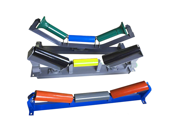
Understanding the cutting machine is only one part of manufacturing knowledge. Conveyor roller production also involves shaft processing, bearing assembly, welding, and inspection, which means decisions made at the cutting stage can affect several later operations.
A pipe cutting machine manufacturer familiar with this workflow can evaluate cutting quality according to what the finished blank needs to do next. Length consistency, burr control, end-face condition, and material handling become part of an integrated production strategy rather than isolated machine specifications.
This process perspective is particularly useful when planning batch manufacturing because overall production stability depends on how effectively one machine transfers workpieces to the next.
Conclusion
A pipe cutting machine manufacturer should be evaluated according to the complete relationship between machine design, steel pipe specifications, cutting quality, automation, maintenance, and downstream manufacturing. Maximum diameter alone provides only a small part of the information needed to determine whether equipment is suitable for conveyor roller production.
For round steel pipe, a stationary-workpiece and rotating-tool structure provides a practical method for repeated straight cutting. Servo feeding and ball-screw transmission control material position, hydraulic self-centering clamping stabilizes the pipe, PLC control coordinates the machine cycle, and adjustable spindle conditions support different processing requirements.
The strongest machine selection starts with the actual roller tube and follows the workpiece through the complete production process. When cutting equipment creates predictable blanks for double-end machining, assembly, welding, and inspection, it becomes a controlled first stage within a larger conveyor roller manufacturing system.
FAQ
What should be checked when evaluating a pipe cutting machine manufacturer?
Evaluation should cover the real pipe diameter and wall-thickness range, feeding method, clamping structure, cutting principle, spindle control, tooling, machine rigidity, PLC system, maintenance accessibility, and compatibility with downstream production. The machine should be assessed against actual steel pipe specifications rather than maximum values alone.
Why is servo feeding important in an automatic pipe cutting machine?
Servo feeding controls how far the steel pipe moves before each cutting cycle, making it one of the main factors affecting finished blank length. When combined with a ball screw and stable mechanical guides, the system can reproduce defined feeding movements across repeated workpieces while dimensional inspection confirms actual cutting results.
Why does the pipe remain stationary during cutting?
Keeping the pipe stationary avoids rotating the entire length of raw steel stock. The tube only moves longitudinally during feeding, after which hydraulic clamping holds it securely while the tool holder rotates around the cutting area. This structure is particularly suitable for repeated straight cutting of long round steel pipe.
What pipe range does the QZ160 cutting machine support?
The QZ160 is specified for round steel pipe diameters of approximately Φ60–159 mm and wall thicknesses from 3 to 8 mm. It uses servo motor and ball-screw feeding, self-centering hydraulic clamping, variable-frequency spindle control, and a rotating-tool structure for repetitive steel tube preparation.
Why should pipe cutting be planned together with roller manufacturing?
The cut tube becomes the starting workpiece for later roller processes such as double-end tube machining, component assembly, bearing setting, welding, and inspection. If cutting creates inconsistent blank lengths or poor end conditions, later machines receive unstable inputs, so cutting quality influences the complete production sequence.
 English
 French
 Spanish