

Table of Contents
Introduction
Chamfering seems like a small machining operation, but for conveyor roller shafts and other long cylindrical parts, the condition of both shaft ends can directly influence later positioning, assembly, bearing installation, and inspection. When flat facing, chamfering, and center-hole machining are completed separately, every additional setup creates another opportunity for dimensional variation between the two ends of the same workpiece.
For this reason, evaluating a chamfering machine manufacturer should focus on much more than whether the equipment can create a beveled edge. Machine structure, double-end synchronization, workpiece centering, clamping, automatic feeding, cutting-tool arrangement, PLC control, dimensional range, and machining repeatability all affect whether the equipment is appropriate for repetitive shaft production.
For conveyor roller manufacturing in particular, the requirement is highly specific. The machine needs to process long shaft products rather than general sheet metal or unrelated components. A suitable system can complete flat-head machining, chamfering, and center-hole preparation at both ends within one coordinated process, reducing repeated workpiece handling while maintaining a common machining reference.
What Should a Chamfering Machine Manufacturer Actually Provide?
A chamfering machine manufacturer serving roller shaft production should be able to connect the machining function with the actual geometry of the finished shaft. The equipment is not simply expected to remove a sharp corner; it needs to hold a long cylindrical workpiece accurately, establish the centerline, machine both ends, and maintain stable dimensional relationships throughout repetitive production.
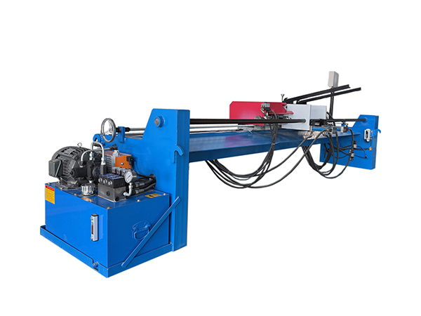
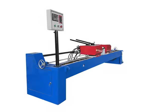
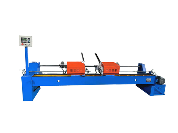
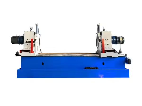
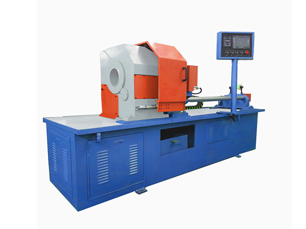
The existing flat head chamfer and center hole machine combines several shaft-end operations in one machine. Both ends can be processed simultaneously to create flat end faces, chamfers, and center holes, while PLC control coordinates automatic feeding, clamping, and tool advance and return.
This combined structure is particularly relevant for conveyor roller shafts because the two ends normally contain corresponding geometric features. Processing them within one machine setup reduces the need to reverse the shaft repeatedly and re-establish the machining reference for each operation.
Check 1: Is the Machine Designed for the Actual Workpiece?
The first factory check should determine whether the machine was developed around the intended workpiece rather than adapted from a general machining platform without considering shaft geometry. Conveyor roller shafts are relatively long compared with their diameter, so their support, centering, clamping, and double-end accessibility create different requirements from short components.
The TPD-2040 configuration is designed for shaft products with diameters from approximately Φ20 to Φ40 mm and processing lengths from 280 to 2200 mm. This range corresponds directly with the type of long shaft components commonly used in roller manufacturing.
Machine evaluation should therefore begin with the workpiece drawing. Shaft diameter, overall length, required chamfer geometry, end-face condition, center-hole requirement, and downstream operation should all be defined before the equipment configuration is considered.
A manufacturer that begins with the real workpiece is more likely to establish a suitable relationship between the spindle, fixture, support structure, tool path, and finished geometry.
Why Shaft-End Processing Needs a Dedicated Approach
Long roller shafts can require more than one end feature. The same workpiece may need a flat end face for dimensional control, a chamfer to remove the sharp corner and improve later handling or assembly, and a center hole to support subsequent machining or positioning.
Completing these operations on separate machines can increase handling and setup variation. Every time the shaft is moved, the relationship between the two ends needs to be established again.
A dedicated machine combines these operations around one central workpiece reference. This is particularly useful in batch manufacturing, where the objective is not simply to produce one accurate shaft but to reproduce the same end geometry across many components.
Check 2: Can Both Shaft Ends Be Processed Simultaneously?
Double-end processing is one of the most important features to evaluate when the workpiece contains corresponding geometry at both ends.
If each end is machined separately, the operator must reposition or reverse the workpiece before the second operation. This creates additional handling and increases dependence on repeated setup accuracy.
The existing machine structure allows both ends to complete flat facing, chamfering, and center-hole processing simultaneously. The machining centerline remains referenced to the same workpiece position, which helps maintain a more consistent relationship between the left and right ends.
For conveyor roller shafts, this matters because opposite ends ultimately interact with the same roller assembly and conveyor mounting structure. Dimensional consistency therefore needs to be evaluated across the complete shaft rather than on one end alone.
Check 3: How Does the Machine Maintain the Workpiece Centerline?
Accurate shaft-end machining depends on maintaining a predictable relationship between the workpiece centerline and the cutting system.
A long cylindrical shaft that is positioned off-center can produce different machining conditions at the two ends even when the programmed movements remain identical. For this reason, centering and clamping should be considered fundamental parts of the machining system.
The machine structure is designed so the centerline relationship between the workpiece and cutting plate remains stable during processing. Automatic clamping then holds the shaft in position before both cutting units begin their machining cycle.
This combination reduces the amount of manual centering required during repetitive production and creates a more stable starting position for the cutting operation.
Check 4: Does the Machine Combine Chamfering With Other Required Operations?
A useful shaft-processing machine should reflect the actual sequence required by the finished component. If flat facing, chamfering, and center-hole machining are all needed, completing them in separate setups can create unnecessary handling.
The existing equipment combines these operations into one process. The cutting system can create a flat end surface, remove material to form the required chamfer, and produce the center hole while the shaft remains in the same general machine setup.
A chamfer is a beveled transition between two surfaces, but in industrial shaft production its function should be considered together with the surrounding geometry. Chamfer size, end-face position, shaft diameter, and center-hole location all need to correspond with the final component drawing.
Combining these features therefore improves process organization, but dimensional inspection remains necessary to confirm that each operation produces the required geometry.
Flat Head Machining Creates a Dimensional Reference
Flat-head processing establishes the end surface of the shaft. This surface can influence overall component length and create a reference for later machining or assembly.
If the two shaft ends are processed independently, variation in tool position or workpiece location can create differences in final length. Double-end processing helps manage both surfaces within one coordinated setup.
For conveyor roller production, this dimensional relationship matters because shaft length influences how the finished roller fits the conveyor structure. The end surfaces should therefore be treated as functional geometry rather than cosmetic finishing.
Chamfering Removes More Than a Sharp Edge
Chamfering is often associated with deburring, but industrial shaft chamfers can perform several functions at once. They remove sharp transitions, improve workpiece handling, provide a controlled lead-in geometry, and can prepare the shaft for later assembly operations.
The important distinction is that chamfering creates a defined geometric feature rather than simply removing random burrs. The amount of material removed, the location of the chamfer, and its relationship with the shaft diameter should remain consistent from workpiece to workpiece.
For batch roller shaft production, machine-controlled chamfering provides a more repeatable method than relying entirely on hand grinding or manual edge finishing.
Center Holes Support Later Machining Requirements
A center hole can provide an accurate reference point for later shaft machining, inspection, or positioning depending on the production route.
Its value depends on concentricity with the shaft. A center hole positioned away from the intended axis can affect later operations that use it as a reference.
Combining center-hole preparation with flat-head and chamfer machining means these features are established while the shaft remains within one controlled process.
This reduces the number of independent setups and helps maintain a common geometric relationship between the workpiece and the machined features at both ends.
Check 5: Is Automation Applied to the Correct Operations?
Automation is useful when it standardizes repetitive actions that would otherwise depend heavily on manual operation. In shaft-end processing, feeding, positioning, clamping, tool advance, machining, retraction, and unloading can all influence the consistency of the cycle.
The TPD-2040 uses PLC control together with automatic feeding, automatic clamping, and simultaneous advance and return of the cutting units at both ends. Automatic loading and unloading can also form part of the machine operation.
The value of these functions is not simply reduced operator involvement. Their main advantage is that similar workpieces can follow a more consistent sequence throughout the production batch.
Automation should still be supported by correct workpiece dimensions, suitable tooling, stable fixtures, and routine inspection because a control system cannot correct poor mechanical preparation automatically.
A Typical Shaft-End Machining Cycle
A well-organized machining cycle establishes a clear sequence from loading through final inspection.
| Stage | Machine Function | Purpose |
|---|---|---|
| Loading | Shaft enters work area | Prepare machining cycle |
| Positioning | Establish shaft location | Maintain machining reference |
| Clamping | Secure cylindrical workpiece | Prevent movement |
| Double-end facing | Machine both end surfaces | Control shaft-end geometry |
| Chamfering | Create beveled edges | Form controlled end transition |
| Center-hole machining | Process both center locations | Create machining reference |
| Tool return | Retract cutting units | Complete machining |
| Unloading | Release finished shaft | Prepare next workpiece |
| Inspection | Verify dimensions | Confirm process stability |
The benefit of the sequence comes from maintaining the relationship between these operations instead of treating each one as an unrelated step.
Check 6: Can the Machine Hold Suitable Working Accuracy?
Machine accuracy should be evaluated in relation to the final shaft requirement rather than as an isolated specification.
The TPD-2040 lists working accuracy of approximately ±0.1 mm. Achieving repeatable results within the intended range depends on more than control-system settings. Workpiece condition, centering, clamping, tool wear, fixture accuracy, machine rigidity, and maintenance all influence the actual finished component.
A chamfering machine manufacturer should therefore be able to explain how these mechanical elements work together. Accuracy comes from the entire machining system, not from the PLC alone.
For batch production, first-piece verification and periodic dimensional checks are particularly important because they confirm that the process continues to reproduce the intended geometry over time.
Check 7: Is the Machine Integrated With Roller Shaft Production?
A shaft-end machine creates the most value when its output matches the processes before and after it.
Roller shafts may require flat-slot milling, through-flat milling, circlip grooving, end chamfering, center-hole preparation, or other features depending on the final roller design. These processes should not be arranged randomly because each operation changes the workpiece condition received by the next machine.
The wider conveyor roller manufacturing machinery includes dedicated equipment for several of these shaft and roller-processing stages. Planning them as a connected route helps manufacturers maintain consistent dimensional references from raw shaft material through final assembly.
A shaft-end chamfering machine should therefore be evaluated by how naturally it fits this workflow rather than only by its individual machining cycle.
How Chamfering Fits With Flat Slot Milling
Some roller shafts require flat surfaces at their ends so the finished roller can fit correctly into the conveyor support structure.
Flat-slot milling and chamfering perform different functions. Milling establishes the mounting geometry, while chamfering and flat-head processing prepare the shaft end itself.
If both operations are required, their sequence should follow the component drawing and the reference surfaces used by each machine.
Maintaining consistent shaft length and centerline alignment across these stages reduces the risk that one machining process disrupts geometry established earlier.
How Chamfering Fits With Circlip Grooving
Certain roller shafts require retaining grooves for circlips or related components. Groove position is normally defined in relation to the shaft end, which means end-face consistency can influence the dimensional reference used during grooving.
When flat-head processing creates stable shaft-end surfaces, later machining operations have a more predictable reference from which groove positions can be established.
This illustrates why apparently separate machining steps should be viewed as one production route. The quality of one feature can influence how reliably the next feature is positioned.
Why Working Pressure Matters
The TPD-2040 lists a working-pressure range of approximately 4–8 MPa. This pressure supports the pneumatic or machine actuation required during clamping and processing.
The listed range should not be interpreted independently from machine condition. Stable pressure delivery is necessary for repeatable movement and workpiece holding, while leaks or irregular supply can alter the behavior of clamping and actuation components.
Routine maintenance should therefore include pressure-system inspection alongside cutting tools, fixtures, guides, and electrical controls.
Stable machining depends on both the cutting process and the systems that position and secure the workpiece.
Tooling Design Influences Chamfer Consistency
The cutting tool creates the actual machined geometry, which makes tooling selection and condition important parts of the process.
The machine uses a specially designed cutting plate with standardized blades, allowing blade adjustment and replacement to be handled more systematically. Standardized tooling can simplify maintenance and help reduce variation caused by inconsistent manual tool preparation.
Blade condition should still be monitored during production. Wear can gradually change the chamfer surface, dimensional relationship, or machining load even when every machine setting remains unchanged.
Finished workpieces therefore provide valuable feedback about tooling condition.
Machine Rigidity and Long Shaft Processing
Long shafts can create machining challenges because the workpiece must remain stable over a relatively large span while both ends are processed.
The machine structure and supports need sufficient rigidity to keep the shaft aligned during clamping and cutting. Excessive movement can influence flatness, chamfer consistency, or center-hole position.
Support points should therefore correspond with the shaft length and diameter being processed. A setup suitable for a short shaft may require adjustment when a substantially longer component enters production.
Machine rigidity should be considered together with workpiece support rather than judged only by frame size.
Why Automatic Loading Can Improve Batch Production
Manual loading can work effectively in smaller batches, but repeated handling of long shafts requires operator time and introduces another source of positioning variation.
Automatic loading and unloading can create a more organized material flow when production volume justifies it. Workpieces enter the machining position through a consistent sequence, are clamped and processed, and then leave the machine for the next manufacturing stage.
The benefit is strongest when surrounding processes are also organized. Increasing the output of one machine provides limited value if the next stage cannot process the completed shafts at a compatible rate.
Automation should therefore support the overall production rhythm rather than operate as an isolated feature.
First-Piece Inspection After a Setup Change
When shaft diameter, length, tooling, or machining requirement changes, the first completed workpiece should receive additional dimensional inspection.
Operators can verify overall length, end-face condition, chamfer geometry, center-hole location, and any other dimensions that influence the following process. This confirms whether the new machine setup matches the actual shaft rather than relying entirely on previous settings.
Once the first piece has been verified, continuous production can proceed with periodic inspection.
This approach is particularly valuable in facilities producing several roller shaft specifications on the same machine because every changeover introduces a new combination of workpiece and setup conditions.
Diagnosing Uneven Chamfers
If the chamfer differs between opposite shaft ends, troubleshooting should begin with workpiece positioning and centerline alignment.
Clamping condition, cutting-tool position, blade wear, machine adjustment, and shaft straightness should then be inspected. Changing cutting parameters before checking these mechanical factors can make the original problem more difficult to identify.
If variation develops gradually across a production batch rather than appearing immediately after setup, tool wear or fixture condition becomes more likely.
A structured troubleshooting process helps distinguish machine adjustment problems from component or tooling problems.
Diagnosing Inconsistent Shaft Length
Flat-head machining can influence the final end-to-end dimension of the shaft. If completed shafts begin showing inconsistent length, several process elements should be checked.
The initial raw shaft dimensions, workpiece positioning, clamping, cutting-unit movement, tooling condition, and machine reference positions all contribute to the final result.
Both ends should be evaluated together because the finished length is created by their combined geometry.
This is another reason double-end machining needs a common dimensional control strategy instead of treating each spindle independently.
Diagnosing Center-Hole Position Problems
A center hole needs to correspond with the intended shaft axis. If it appears offset or inconsistent between workpieces, the problem can influence later machining operations that depend on the center as a reference.
Workpiece centering should be checked first, followed by clamping alignment, cutting-tool position, shaft straightness, and machine condition.
The problem should not automatically be attributed to the center-hole tool itself because the final location depends on the complete relationship between the shaft and machine centerline.
A stable setup ensures that center-hole machining reflects the actual geometry of the workpiece.
Maintenance of the Clamping System
The clamping system repeatedly establishes the physical relationship between the shaft and machine. Wear or contamination on contact surfaces can therefore influence machining accuracy even when the control program remains unchanged.
Fixtures and clamps should be cleaned regularly and inspected for looseness, damage, or uneven wear. Actuation pressure should also remain within the required operating condition.
When a machine processes several shaft diameters, adjustment points deserve particular attention because frequent changeovers can gradually introduce looseness if mechanical components are not checked.
Reliable clamping provides the foundation for consistent double-end machining.
Maintenance of Cutting Tools and Guides
Cutting tools should be inspected according to both working time and the condition of finished components. A blade can remain operational while its edge gradually changes enough to influence chamfer quality.
Guides and moving components also require suitable lubrication and cleanliness. Machining debris should not be allowed to accumulate where it can interfere with movement, fixtures, sensors, or workpiece positioning.
Preventive inspection is especially useful in batch manufacturing because a gradual mechanical change can otherwise affect many shafts before the problem becomes visually obvious.
What Technical Data Should Be Reviewed?
A meaningful evaluation of a chamfering machine should use the actual shaft-processing requirements rather than a generic machine checklist.
| Technical Item | TPD-2040 Reference | Why It Matters |
|---|---|---|
| Processing diameter | Φ20–40 mm | Defines suitable shaft range |
| Processing length | 280–2200 mm | Defines workpiece length range |
| Working accuracy | ±0.1 mm | Supports dimensional control |
| Working pressure | 4–8 MPa | Supports machine actuation |
| Control method | PLC | Coordinates automatic cycle |
| End processing | Both ends simultaneously | Reduces repeated setup |
| Operations | Flat head, chamfer, center hole | Combines shaft-end processes |
| Material handling | Automatic loading/unloading available | Supports repetitive production |
These parameters should be compared with the real shaft drawing and production route rather than evaluated only as isolated maximum values.
Manufacturer Evaluation Should Include Process Understanding
A chamfering machine manufacturer should understand why the shaft is being processed, what operations occur before chamfering, and what the workpiece needs to do afterward.
For conveyor roller shafts, this can include relationships with flat milling, circlip grooving, bearing assembly, roller installation, and final dimensional inspection.
This process knowledge matters because machine configuration should support the finished component rather than simply demonstrate that the cutter can remove material.
A technically suitable machine is one that fits naturally into the existing production route and creates geometry that the next process can use consistently.
Avoid Confusing Shaft Chamfering With Tube Chamfering
Chamfering terminology can describe several different workpieces, but the machine discussed here is specifically designed mainly for shaft products.
This distinction is important for equipment selection. A machine intended to process long solid or shaft-type components is not automatically equivalent to equipment designed primarily for pipe or tube end preparation.
The workpiece support, clamping, centerline, cutting-tool arrangement, and required end features can all differ.
When evaluating equipment, the exact workpiece should therefore remain part of the keyword and specification context. For conveyor roller manufacturing, the relevant application is shaft-end flat facing, chamfering, and center-hole preparation.
Why This Machine Is Relevant to Conveyor Roller Manufacturing
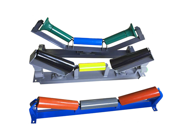
A finished conveyor roller depends on the dimensional relationship between the roller tube, shaft, bearings, housings, seals, and mounting features. Shaft-end geometry is part of this relationship because it influences both manufacturing references and final installation.
A double-end machining system is well suited to this component because the roller shaft itself is symmetrical and contains corresponding features at opposite ends.
By combining flat-head processing, chamfering, and center-hole machining, the equipment creates a controlled intermediate shaft before later assembly or additional processing.
This makes the machine part of a genuine conveyor roller manufacturing workflow rather than a generic metal-finishing application unrelated to the website’s product focus.
Conclusion
Evaluating a chamfering machine manufacturer for conveyor roller shaft production requires much more than confirming that the machine can create a beveled edge. The equipment needs to match long shaft geometry, maintain a stable centerline, clamp the workpiece reliably, process corresponding features at both ends, and integrate with surrounding roller manufacturing operations.
The TPD-2040 configuration combines flat-head machining, chamfering, and center-hole preparation while processing both ends simultaneously. Its working range of approximately Φ20–40 mm diameter and 280–2200 mm length, PLC control, automatic feeding and clamping, and ±0.1 mm working-accuracy specification reflect the requirements of repetitive shaft processing.
The most important evaluation principle is therefore process compatibility. When workpiece geometry, machine structure, tooling, automation, inspection, and upstream and downstream operations are considered together, shaft-end machining can become a controlled and repeatable part of conveyor roller production.
FAQ
What type of workpiece is this chamfering machine designed to process?
This machine is mainly designed for shaft products rather than being a general-purpose tube chamfering system. The TPD-2040 supports shaft diameters of approximately Φ20–40 mm and lengths from 280 to 2200 mm, making it suitable for long cylindrical components such as shafts used in conveyor roller manufacturing.
What operations can the machine complete on the shaft ends?
The machine can complete flat-head machining, chamfering, and center-hole processing at both ends within one coordinated setup. Combining these operations reduces repeated workpiece repositioning and helps maintain a more consistent dimensional relationship between the two corresponding ends of a long roller shaft.
Why is double-end processing important for conveyor roller shafts?
Roller shafts normally contain corresponding geometry at opposite ends, so machining both sides within one setup reduces the need to reverse and relocate the workpiece repeatedly. A common machine reference helps maintain consistency in shaft length, end-face position, chamfer geometry, and center-hole location across batch production.
What accuracy and working range does the TPD-2040 provide?
The TPD-2040 lists working accuracy of approximately ±0.1 mm, a processing diameter range of Φ20–40 mm, processing lengths from 280 to 2200 mm, and working pressure of 4–8 MPa. Actual finished-part consistency also depends on tooling, clamping, workpiece condition, setup, and maintenance.
What should be checked when evaluating a chamfering machine manufacturer?
Evaluation should consider actual workpiece range, double-end machining capability, centering and clamping, available end-processing operations, PLC control, tooling design, working accuracy, automatic feeding, maintenance access, and how well the machine fits upstream shaft machining and downstream roller assembly processes.
 English
 French
 Spanish