

Table of Contents
Introduction

Conveyor roller manufacturing does not end when the tube and shaft have been machined. The prepared components still need to be assembled into a stable structure in which the shaft, bearing housing, bearing, roller shell, and related parts maintain the intended relationship. When roller production moves into repeated batches, this assembly stage becomes increasingly important because small differences in positioning or pressing can be reproduced across many finished rollers.
A conveyor roller assembly machine provides a controlled way to complete the bearing-setting stage. Instead of installing components at each end through separate manual operations, a double-end hydraulic system can position the roller along a defined machine centerline and press both sides within one coordinated cycle.
The objective is not simply to apply force. Consistent assembly depends on component dimensions, pressing-axis alignment, workpiece support, bearing housing structure, hydraulic control, and inspection. This guide explains how a conveyor roller assembly machine works, why double-end pressing is suitable for roller production, and how the assembly stage connects with upstream machining and downstream processing.
What Is a Conveyor Roller Assembly Machine?
A conveyor roller assembly machine is specialized equipment used to fit bearing-related components into a prepared conveyor roller structure. The machine is designed around the long cylindrical geometry of the roller and provides a defined relationship between the workpiece, pressing heads, supports, and machine centerline.
The double-end hydraulic roller assembly process uses hydraulic press-fitting while the roller is positioned between opposing pressing spindles. Both heads can operate simultaneously, allowing corresponding components at the two ends of the roller to be assembled within the same working cycle.
This configuration is different from a general workshop press because the equipment is specifically arranged for conveyor rollers. Roller diameter, roller length, bearing housing structure, pressing position, and spindle alignment all form part of the machine configuration.
For batch production, the main advantage is repeatability. Once the machine has been correctly adjusted for a roller specification, subsequent workpieces can follow the same mechanical sequence.
Why Bearing Assembly Matters in Conveyor Roller Production
A conveyor roller depends on the relationship between its rotating and supporting components. The roller shell needs to rotate around the shaft through the bearing arrangement, while the bearing housing and related elements keep those components positioned within the intended structure.
A mechanical bearing is designed to constrain relative motion while reducing friction between moving parts. In a conveyor roller, correct bearing position therefore becomes an important part of the complete assembly geometry.
If one bearing-related component is pressed into a different position from another, the finished assembly may no longer reproduce the geometry established during tube and shaft machining. This is why bearing setting should be treated as a controlled manufacturing process rather than a final manual fitting task.
A conveyor roller assembly machine helps establish repeatable workpiece positioning before pressing begins, making the operation easier to control across multiple rollers.
How the Conveyor Roller Assembly Process Works
The process begins after the main roller components have already been prepared. The roller tube, shaft, bearing housing, and other required parts need to match their intended dimensions before entering the assembly station.
The operator loads the roller into the machine and positions it along the working centerline. Supports hold the cylindrical workpiece in a stable condition while the two pressing heads align with the assembly positions at opposite ends.
After positioning is confirmed, the hydraulic system moves the pressing heads toward the roller. Both sides can operate simultaneously so the corresponding components are fitted during one coordinated cycle. Once the required position has been reached, the heads retract and the roller can move to inspection or the next manufacturing stage.
This sequence reduces the need to assemble one end, reverse or reposition the roller, and then establish a second independent setup.
Why Double-End Pressing Fits Conveyor Roller Geometry
Conveyor rollers are naturally suited to double-end processing because many of their structural features are symmetrical. Bearing-related components are normally located at both ends of the cylindrical shell, making it practical to establish both assembly positions within one machine structure.
When separate presses or manual operations are used, each side can develop its own positioning reference. The workpiece may also need additional handling between the two operations.
A double-end conveyor roller assembly machine keeps the roller in one defined position while pressing force is applied from opposite directions. This reduces unnecessary workpiece movement and creates a common mechanical reference for both sides.
The value of this structure becomes more apparent during batch production. Repeated rollers can be assembled through the same setup rather than rebuilding the relationship between the roller and pressing equipment for every end.
Hydraulic Press-Fitting in Roller Assembly
Hydraulic systems are well suited to assembly operations requiring controlled linear movement. Hydraulic cylinders convert fluid pressure into the force and motion used to advance the pressing heads toward the workpiece.
In conveyor roller assembly, this allows the machine to move both pressing heads through a defined stroke while the roller remains supported between them.
Stable hydraulic movement helps make the pressing operation more repeatable, but hydraulic force should not be considered separately from component dimensions. A part that has been machined incorrectly should not require the press to compensate for the dimensional problem.
The pressing system should therefore work with correctly prepared components. Hydraulic control completes the intended fit, while upstream machining determines whether those components arrive at the assembly station in a predictable condition.
Pressing Spindle Alignment
The two pressing spindles need to act along a controlled axis. If one spindle is significantly offset from the other, the forces applied to the two ends may no longer follow the intended centerline of the roller.
For the TY-220×2200 configuration, the specified coaxial deviation between the two pressing spindles is no more than 0.1 mm. This parameter illustrates why a conveyor roller assembly machine should be evaluated by geometry as well as pressing capability.
Machine alignment also needs to be supported by correct workpiece positioning. Even accurately aligned spindles cannot provide a stable process if the roller is loaded away from the intended centerline.
Supports, fixtures, pressing surfaces, and the workpiece itself therefore need to function as one aligned assembly system.
Matching the Machine to Roller Diameter
Roller diameter determines how the workpiece interacts with the machine supports and pressing arrangement. A smaller roller and a larger roller cannot simply be treated as identical workpieces because their center position and supporting conditions may differ.
The TY-220×2200 configuration is designed for roller diameters from Φ76 to Φ219 mm. When changing between specifications, the machine setup should ensure that the new workpiece remains properly centered relative to the pressing spindles.
Support positions should also prevent unwanted movement without deforming the roller shell.
After a significant diameter adjustment, the first completed roller should receive additional inspection before continuous batch processing begins. This confirms that the mechanical setup corresponds with the new workpiece dimensions.
Roller Length and Machine Adjustment
Roller length is another important factor because conveyor rollers can vary substantially according to the structure in which they are installed.
The same TY-220×2200 model supports roller lengths from 200 to 2200 mm. This requires the pressing arrangement and workpiece support system to accommodate both relatively short and long cylindrical assemblies.
Long rollers require particular attention to support because the middle of the workpiece should remain stable while pressing forces act from both ends.
When switching between lengths, operators should verify pressing-head positions, support locations, and the relationship between the roller centerline and machine axis. A documented setup procedure can make repeated specification changes easier to reproduce.
Bearing Housing Structure and Assembly
The bearing housing forms an important interface between the bearing and roller shell. Different roller structures may use cast iron or pressed bearing housings, and these variations influence how the assembly should be supported during pressing.
The machine needs to transfer force through appropriate contact areas rather than applying pressure to surfaces that are not intended to carry the assembly load.
This makes tooling and pressing-head geometry important. The equipment should be configured around the actual roller drawing, bearing housing dimensions, shaft arrangement, and component position.
When a manufacturer changes to a different bearing housing design, machine adjustment may involve more than roller length or diameter. Pressing interfaces may also need to be checked before the new production batch begins.
Why Component Dimensions Must Be Controlled Before Assembly
An assembly machine works best when the parts entering the station already match their machining requirements.
If the shaft diameter varies, the bearing housing position changes, or the roller tube has inconsistent end geometry, pressing behavior can differ from one workpiece to another even when the machine settings remain unchanged.
Increasing hydraulic force is not a reliable way to solve these upstream problems. It can hide the true source of variation instead of correcting it.
For this reason, dimensional inspection should occur before final assembly. Tube-end machining, shaft processing, bearing housing preparation, and other relevant features should be checked close to the stage where they are produced.
A conveyor roller assembly machine then performs its intended role: joining correctly prepared components through a controlled pressing process.
Connecting Assembly With Tube Processing
The roller shell normally reaches the assembly stage only after tube cutting and additional end processing have been completed.
Cutting establishes the initial shell length, while double-end machining can prepare the tube ends for bearing housing or related component installation. Any variation created during these operations affects the workpiece presented to the assembly machine.
A tube that is too short, unevenly machined, or dimensionally inconsistent can change how later components sit inside the roller structure.
This is why roller manufacturing should be treated as a connected sequence rather than a collection of unrelated machines. The output from one operation becomes the starting condition for the next.
Connecting Assembly With Shaft Processing
The shaft follows a separate machining path before meeting the roller tube during assembly. Depending on the design, the shaft may require flat milling, through-flat processing, retaining grooves, chamfering, center holes, or other prepared features.
These operations establish the geometry that will later interact with the bearing arrangement and conveyor mounting structure.
If shaft dimensions vary between workpieces, bearing assembly may no longer behave consistently. The same hydraulic press settings can produce different mechanical conditions because the incoming parts are different.
For this reason, shaft machining and roller assembly should share a common dimensional-control strategy. Accurate upstream machining reduces the amount of variation the assembly station needs to manage.
Positioning Long Cylindrical Workpieces
A conveyor roller assembly machine needs to support the workpiece along a stable axis before the pressing cycle begins.
Long cylindrical rollers can sag or shift if the support points are inappropriate. Small positioning differences may then influence the relationship between the bearing assembly and pressing heads.
Supports should hold the roller securely while allowing the pressing system to operate without interference. Their positions may need adjustment when moving between significantly different roller lengths.
Operators should also follow a consistent loading procedure. Repeatedly placing the roller in the same mechanical reference condition makes the pressing cycle easier to reproduce from one workpiece to another.
Manual Loading With Controlled Pressing
The existing assembly equipment uses manual loading combined with semi-automatic hydraulic pressing. This structure provides flexibility while keeping the critical pressing movement under machine control.
Manual loading allows operators to handle different roller dimensions without requiring a fully automated transfer system. Once the workpiece has been positioned, the double-end hydraulic cycle performs the assembly operation.
This can be particularly suitable for factories producing several roller specifications in batches.
The important point is that manual loading should still follow a defined procedure. Workpiece position, support, and initial alignment need to remain consistent before every pressing cycle begins.
PLC Control and Repeatable Operation
PLC control coordinates the sequence of the conveyor roller assembly machine. It allows machine actions to occur in a defined order rather than relying on repeated independent manual commands.
Once the roller has been positioned, the control system can coordinate hydraulic movement, pressing completion, spindle return, and other machine functions according to the established sequence.
The advantage is repeatability. Similar rollers can pass through the same operating logic during a production batch.
However, PLC control cannot correct a mechanical setup problem. If a fixture has moved, a support is incorrectly positioned, or incoming components do not meet the intended dimensions, repeating the same program will not eliminate the variation.
Pressing Force and Component Fit
The TY-220×2200 model has a listed maximum pressing force of 4000 kgf and a hydraulic working-pressure range of 2.5–4.5 MPa.
These figures describe the capability of the machine, but they should not be interpreted as a requirement to use maximum force during every assembly.
The appropriate pressing condition depends on the bearing arrangement, housing design, mating dimensions, material, and required final position.
If assembly resistance suddenly changes during production, operators should inspect component dimensions and workpiece alignment before changing hydraulic settings. A stable process relies on understanding why the pressing condition has changed rather than simply applying more force.
Assembly Sequence Within Roller Manufacturing
A complete roller manufacturing process may involve multiple machine stages before and after bearing setting.
Typical operations include tube cutting, tube-end machining, shaft preparation, bearing assembly, welding, and final inspection. Depending on the roller design, additional processing can also be required.
The roller manufacturing equipment used across these stages should operate as a coordinated sequence in which each process prepares the workpiece for the next.
For example, consistent tube and shaft machining creates more predictable assembly conditions, while correctly assembled components give the welding stage a stable joint position.
This process relationship is more important than optimizing one machine in isolation.
Balancing Assembly With Upstream Production
A fast assembly cycle does not automatically create an efficient production line. If tube processing or shaft machining cannot supply prepared components at a similar rate, the conveyor roller assembly machine may spend significant time waiting.
The opposite can also occur. If upstream machines produce components faster than the assembly station can handle them, unfinished workpieces may accumulate.
Manufacturers should therefore compare cycle times and specification-change requirements across the complete roller production process.
Balanced workflow makes it easier to identify where additional capacity or process improvement is actually needed.
Changing Between Roller Specifications
Factories manufacturing several roller models need a repeatable method for changing machine setup.
A specification change can affect roller supports, pressing-head positions, fixtures, workpiece centerline, and the position of bearing-related components.
Frequently produced roller designs can benefit from documented setup conditions so operators do not need to rebuild the process from the beginning every time a product returns to production.
After an adjustment, the first completed roller should be inspected carefully. Once the setup has been confirmed, continuous production can proceed under the validated conditions.
This approach combines machine flexibility with controlled batch processing.
Common Causes of Assembly Variation
Inconsistent pressing does not always originate from the conveyor roller assembly machine itself.
Incoming component dimensions may differ, the workpiece may be positioned incorrectly, fixtures can wear, hydraulic behavior can change, or pressing surfaces may become contaminated.
Spindle alignment and support position should also be considered when repeated differences appear between the two ends of the roller.
A structured troubleshooting process begins with the components, then checks workpiece positioning, machine supports, pressing interfaces, spindle alignment, hydraulic operation, and the finished assembly.
Following the process in order makes the true source of variation easier to identify.
Inspecting the Roller After Assembly
Inspection should take place before the workpiece moves into the next manufacturing stage.
The exact requirements depend on the roller design, but useful checks may include bearing position, component symmetry, shaft relationship, visible assembly condition, and roller rotation.
Because both ends are pressed within one machine cycle, comparing the two sides can provide useful information about machine setup.
If one end repeatedly behaves differently, operators can investigate tooling position, spindle alignment, fixture adjustment, or incoming component dimensions.
Inspection therefore provides feedback about both the finished roller and the condition of the production process.
Maintaining the Hydraulic System
Stable hydraulic movement is necessary for predictable pressing.
Cylinders, valves, seals, hydraulic lines, fluid condition, and related components should be inspected according to the machine’s operating requirements. Leakage or irregular movement can alter the way pressing force is applied.
Operators should also observe whether both sides continue to move consistently during repeated cycles.
Changes in pressing behavior, machine sound, movement speed, or return motion should be investigated before they begin to affect a larger production batch.
Hydraulic maintenance is therefore directly connected with assembly consistency.
Maintaining Spindles, Supports, and Fixtures
The mechanical components that position the roller require the same attention as the hydraulic system.
Pressing surfaces should remain clean and correctly aligned. Supports need to hold the workpiece on the intended centerline, while adjustment mechanisms should remain secure after repeated specification changes.
Fixture wear can develop gradually and may not be immediately visible. Periodic dimensional checks can reveal whether machine condition is beginning to influence the finished assembly.
Routine maintenance should therefore include both mechanical inspection and observation of actual roller results.
When a Conveyor Roller Assembly Machine Is Most Useful
This equipment is particularly suitable for repeated production of conveyor rollers that require corresponding bearing-related components at both ends.
Double-end pressing makes effective use of the roller’s symmetrical geometry, while adjustable machine dimensions allow different roller lengths and diameters to be processed within the designed working range.
The equipment becomes especially useful when upstream tube and shaft machining already provide stable components. Predictable incoming workpieces allow the pressing process to operate under more consistent conditions.
For batch manufacturing, this combination creates a structured transition between precision machining and later welding or final inspection.
How to Evaluate a Conveyor Roller Assembly Machine
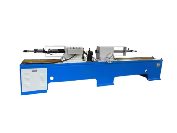
Machine evaluation should begin with the actual roller drawing.
Manufacturers should identify roller diameter, length, bearing housing structure, shaft arrangement, component dimensions, pressing position, and the production stages immediately before and after assembly.
The machine working range, spindle coaxiality, hydraulic system, pressing capability, support structure, PLC control, fixture adjustment, and maintenance requirements can then be compared with those needs.
The most suitable conveyor roller assembly machine is one that integrates naturally into the full manufacturing process and produces a stable assembly for the next operation.
Conclusion
A conveyor roller assembly machine provides a controlled method for setting bearing-related components during roller manufacturing. Double-end hydraulic pressing allows both sides to be processed while the workpiece remains within one machine setup, reducing repeated handling and creating a common mechanical reference.
Reliable assembly depends on more than pressing force. Component dimensions, spindle alignment, roller support, bearing housing structure, hydraulic stability, PLC control, fixtures, and inspection all influence the finished result.
The strongest process also connects assembly with the machining stages that come before it and the operations that follow. When tube preparation, shaft processing, bearing setting, welding, and inspection work as one coordinated system, conveyor roller production becomes easier to control across repeated batches.
FAQ
What is a conveyor roller assembly machine used for?
A conveyor roller assembly machine is used to install bearing-related components into prepared roller assemblies through controlled double-end pressing. The roller is positioned along a defined machine axis while opposing pressing heads fit components at both ends during one coordinated production cycle.
Why is double-end pressing suitable for conveyor roller assembly?
Conveyor rollers normally have corresponding bearing structures at both ends. Double-end pressing keeps the roller in one machine setup while both sides are processed, reducing repeated repositioning and helping maintain a more consistent relationship between the two assembled ends during batch production.
What roller sizes can the TY-220×2200 assembly machine process?
The listed TY-220×2200 configuration supports roller diameters from Φ76 to Φ219 mm and lengths from 200 to 2200 mm. Actual setup should also consider bearing housing geometry, shaft dimensions, workpiece support, pressing position, and the condition of incoming components.
Why is spindle coaxiality important in a conveyor roller assembly machine?
Both pressing heads should act along a controlled axis so assembly force reaches the roller ends consistently. The listed coaxial deviation between the two pressing spindles is no more than 0.1 mm, while correct workpiece support and positioning are also required to maintain alignment during pressing.
What should be inspected after conveyor roller bearing assembly?
Inspection should check bearing position, symmetry between both ends, shaft relationship, visible component condition, and roller rotation where required. Repeated differences can indicate variation in incoming components, supports, fixtures, spindle alignment, hydraulic behavior, or workpiece positioning.
 English
 French
 Spanish