

Table of Contents
Introduction
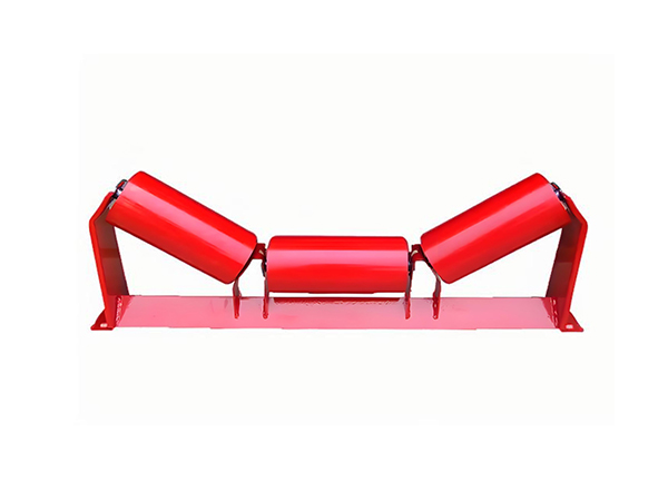
Industrial conveyor rollers are rarely defined by diameter and length alone. A complete roller specification can involve tube material, shaft geometry, bearing size, sealing structure, surface treatment, installation position, applicable standard, and the environmental conditions surrounding the conveyor. When hundreds of similar rollers operate across the same system, consistency between individual components becomes just as important as the specification of one sample.
For this reason, evaluating conveyor rollers suppliers should focus on technical capability rather than a simple product list. The supplier needs to understand how the roller fits into the conveyor, how internal components interact, how different specifications are controlled during manufacturing, and how completed rollers are inspected before they enter service.
The following eight technical checks provide a practical framework for evaluating roller manufacturing capability for mining, quarrying, cement, steel, power, and other industrial belt conveyor applications.
Check 1: Can the Supplier Understand the Complete Roller Specification?
The first technical check should determine whether the supplier can interpret the roller as a complete mechanical assembly. Outside diameter and overall length are important, but they do not define the relationship between the roller tube, shaft, bearing, bearing housing, seal, and conveyor frame.
A useful specification should identify roller diameter, tube length, shaft diameter, overall shaft length, shaft-end geometry, bearing code, sealing arrangement, tube and shaft material, surface finish, idler position, and relevant engineering standard. Where an existing conveyor is involved, bracket geometry and belt width can also influence the final configuration.
The available conveyor roller configurations illustrate this relationship clearly. Different roller diameters can be combined with different lengths, bearing sizes, sealing systems, materials, and idler structures, so the correct combination must be based on the complete application rather than one isolated dimension.
Why Dimensional Drawings Matter
A dimensional drawing creates a common technical reference between engineering, manufacturing, machining, assembly, and inspection. Without that reference, terms such as “standard roller” can be interpreted differently depending on the conveyor system or regional practice.
The drawing should identify the dimensions that influence installation and rotation, particularly shaft-end features and the relationship between the roller body and mounting points. These details become more important when existing conveyor frames have already been manufactured and the replacement roller must reproduce a defined installation geometry.
For repeated production, drawings also help maintain consistency between different manufacturing batches. Machine settings and inspection requirements can be connected to the same documented dimensions instead of relying on informal descriptions.
Check 2: Does the Manufacturing Range Match the Conveyor?
A supplier should have a manufacturing range that corresponds with the actual conveyor rather than simply offering a large number of nominal roller sizes. The current conveyor roller product range includes diameters from approximately 60 to 219 mm and roller lengths from approximately 160 to 2800 mm, covering a broad range of industrial applications.
However, the largest available diameter or longest roller is not automatically the most suitable. Roller dimensions need to correspond with belt width, idler arrangement, shaft structure, bearing capacity, supporting frame, and the operating position of the roller.
For troughing idlers, several rollers may work together to create the belt profile, while return applications can use a different arrangement. Technical evaluation should therefore confirm that the manufacturing range covers not only individual roller dimensions but also the roller structures required across the complete conveyor.
Check 3: Are Bearings, Housings, and Seals Matched as a System?
The internal bearing area determines how the roller shell rotates around the shaft. Bearings, bearing housings, shafts, and seals therefore need to be selected as one compatible system rather than as independent components.
A bearing code affects internal and external dimensions, which can influence shaft size and bearing housing geometry. The sealing structure then needs to match the shaft and housing while protecting the bearing chamber from contamination. Changing one component may therefore require a review of several others.
This becomes especially important in environments containing dust or moisture. Mining, quarrying, and cement conveyors can expose roller ends to continuous contamination, so the sealing system must correspond with the real operating environment as well as the dimensional structure of the roller.
Understanding Bearing Selection
A bearing supports relative motion between components while reducing friction. In a conveyor roller, the bearing allows the cylindrical shell to rotate around the central shaft while carrying the loads transferred through the belt.
Bearing selection should therefore consider shaft diameter, roller geometry, operating load, rotational requirements, housing structure, and sealing arrangement. Choosing a bearing only because it has a larger designation does not necessarily create a more suitable roller.
The current roller range supports several deep-groove ball bearing configurations, allowing the internal structure to be matched with different roller diameters and applications. What matters is whether the complete assembly remains mechanically compatible.
Check 4: Can the Supplier Control Shaft Machining?
The shaft is one of the most important precision components inside a conveyor roller because it establishes the central mechanical axis and connects the roller with the supporting frame. Shaft diameter and length matter, but installation frequently depends on features machined at both ends.
Depending on the conveyor design, these features can include flats, through-flat geometry, retaining grooves, chamfers, or other machined surfaces. Their position needs to remain consistent because corresponding features at opposite ends interact with the same conveyor structure.
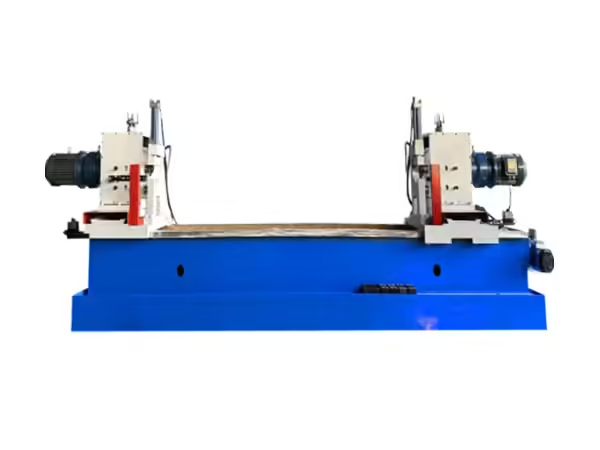
A supplier with dedicated roller shaft machining capability can control these operations around the actual geometry of the workpiece. Double-end machining is particularly useful because corresponding features can be produced within one setup rather than repeatedly repositioning a long shaft between separate operations.
Why Shaft-End Consistency Matters
A roller may have the correct outside diameter and body length but still create installation difficulties if its shaft ends are inconsistent. Differences in flat orientation, groove location, or shaft projection can change how the roller sits in the conveyor bracket.
These problems become more significant when a large conveyor uses many rollers with the same installation geometry. Small dimensional differences can create repeated adjustment during installation or introduce variation across the idler structure.
For this reason, conveyor rollers suppliers should be evaluated on their ability to control shaft machining as well as on their ability to manufacture the outer roller tube.
Check 5: Is Roller Manufacturing Based on Repeatable Processes?
Industrial projects often require many rollers with the same or closely related specifications. Manufacturing capability should therefore be judged by repeatability across a production batch rather than by the appearance of one completed roller.
A controlled process can include tube cutting, tube-end preparation, shaft machining, bearing housing positioning, bearing setting, welding, surface treatment, and final inspection. Each stage creates an input for the next, so dimensional variation introduced early in production can continue into later assembly.
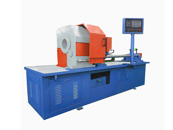
Dedicated roller manufacturing machinery supports this type of controlled workflow by separating tube cutting, shaft machining, bearing assembly, and welding into specialized operations. The benefit lies not simply in automation but in establishing repeatable mechanical references throughout production.
Tube Preparation Affects Every Later Stage
The roller shell begins as tube material, so its length, straightness, diameter, and end condition establish the starting geometry of the finished component. If the tube blank varies significantly, bearing housing positioning and final roller length become more difficult to control.
Automatic tube cutting can create repeated blanks using controlled feeding and clamping, while later double-end machining prepares the tube for bearing-related components. The goal is to move a predictable workpiece from one stage to the next.
For conveyor rollers suppliers, this process relationship is important because the consistency of the finished roller often depends on manufacturing stages that are no longer visible after assembly.
Check 6: Can Different Materials and Surface Conditions Be Controlled?
Roller material should match both mechanical requirements and environmental conditions. Carbon steel is widely used for industrial conveyor rollers, while stainless steel can be relevant where corrosion resistance is more important. Certain roller applications can also use HDPE, nylon, rubber, PVC, or UHMWPE configurations where their material properties correspond with the operating environment.
Material flexibility is useful only when manufacturing processes also match the selected material. A steel roller and an HDPE roller do not necessarily follow identical machining routes, even if their final function within the conveyor is similar.
Surface treatment creates another variable. Powder coating, conventional painting, or galvanized finishes can be selected according to the external environment, but surface protection should not be confused with bearing sealing. External treatment protects exposed surfaces, while the seal performs a different function around the internal bearing chamber.
Check 7: Does the Supplier Understand Different Idler Positions?
A conveyor system can use several roller functions along the same belt path. Carrying rollers support the loaded belt, return rollers support the returning belt, buffer rollers help manage impact around loading zones, while training or self-aligning configurations can support belt guidance.
A supplier should therefore understand the mechanical role of each position rather than treating every roller as an interchangeable cylindrical component. The correct diameter, length, shaft geometry, bearing arrangement, and sealing structure can change depending on where the roller operates.
This is particularly important in large industrial conveyors because loading zones, long carrying sections, return paths, and transfer areas can expose rollers to very different conditions. Technical selection should begin with the operating position before the detailed component specification is finalized.
Carrying and Return Rollers Should Not Be Treated Identically
Carrying rollers support both the moving belt and transported material, so their load conditions are different from those on the return side after material has been discharged. Troughing arrangements also use multiple rollers to create a defined belt profile, which means individual roller dimensions are connected with the geometry of the complete idler set.
Return rollers may experience lower material load but can still encounter contamination from material adhering to the belt. Their sealing, alignment, and rotational condition therefore remain important even when they are not located beneath the loaded belt.
Understanding these differences helps distinguish a technically focused supplier from one that recommends one standard structure for every position.
Check 8: Is Quality Control Integrated Into Manufacturing?
Final inspection is important, but relying only on the completed roller makes it difficult to identify where dimensional variation entered the process. A stronger quality-control approach checks critical dimensions after the manufacturing operations that create them.
Tube length can be inspected after cutting, shaft-end features after machining, bearing housing position during assembly, and weld condition after joining. Final inspection can then focus on the completed roller geometry, rotation, visible condition, and other project-specific requirements.
This staged approach provides more useful process information. If a final roller shows abnormal geometry, manufacturing records can help determine whether the variation began with the tube, shaft, bearing assembly, or another operation instead of treating every problem as a final-assembly issue.
Why Batch Consistency Deserves Special Attention
An individual roller that performs correctly does not automatically prove that the production process is stable. Industrial conveyors frequently use large quantities of similar rollers, which means the manufacturing system needs to reproduce the same dimensional relationships repeatedly.
Batch consistency depends on controlled raw material, machine settings, tooling condition, fixtures, bearing and seal selection, assembly methods, and inspection procedures. Specification changes should also be managed carefully so one roller family does not inherit settings intended for another design.
First-piece inspection after a setup change is particularly useful. It confirms that the new configuration produces the intended result before continuous production proceeds.
How to Evaluate Sealing Capability for Harsh Environments
Dust and moisture can gradually enter the bearing area if the sealing structure is unsuitable or damaged. For bulk-material conveyors, this risk should be evaluated during the specification stage rather than after bearing problems begin.
Different sealing structures create different paths between the external environment and internal bearing chamber. Their effectiveness depends on dimensional accuracy, shaft position, housing geometry, and correct assembly.
Conveyor rollers suppliers serving mining or cement applications should therefore be able to explain how the selected seal corresponds with the complete roller structure. Simply adding more sealing components does not guarantee better performance if those components do not match one another.
How to Assess Manufacturing Flexibility Without Losing Consistency
Industrial conveyor systems often contain several roller specifications, and one facility may need different diameters, lengths, shaft features, bearing arrangements, or idler functions. A capable manufacturing system needs enough flexibility to move between these specifications while maintaining control.
The important issue is how those changes are managed. Documented drawings, machine settings, tooling arrangements, fixtures, and inspection points help operators return to previously validated configurations when the same roller is produced again.
Flexibility without process control can increase variation. Effective customization therefore combines adjustable manufacturing capability with clearly documented technical references.
Technical Documentation to Prepare Before Evaluation
A useful technical review becomes much more efficient when the conveyor information is organized before the roller configuration is discussed. The documentation should identify the conveyor type, belt width, roller position, roller diameter, roller body length, shaft dimensions, mounting geometry, bearing arrangement, sealing structure, material, surface treatment, environmental conditions, and applicable standard.
For an existing installation, drawings or measured dimensions from the current roller can provide an additional reference. However, dimensions should be checked carefully because a heavily worn component may no longer represent its original manufacturing geometry.
The objective is to provide enough engineering information for the roller to be evaluated as part of the conveyor system rather than as an isolated spare component.
What to Check in Roller Drawings
A roller drawing should clearly distinguish between tube length, shaft length, working width, and installation dimensions. Shaft-end flats or grooves should include their relevant dimensions and orientation, while bearing and seal requirements should be associated with the correct roller structure.
If a roller belongs to a troughing set, its relationship with the bracket and neighboring rollers should also be understood. A dimension that appears correct when viewed alone can create a different belt line when installed within the complete set.
Clear drawings reduce ambiguity between engineering and production and also provide a stable basis for inspection when the same roller specification is manufactured again.
Evaluating a Roller for Mining Applications
Mining conveyors may expose idlers to continuous loading, dust, moisture, vibration, and abrasive material. In these conditions, tube and shaft strength remain important, but bearing protection and manufacturing consistency become equally significant.
The supplier should therefore understand the conveyed material and the precise roller position. Loading zones may require a different roller structure from long carrying sections, while return rollers can encounter contamination transferred from the belt.
For large mining conveyors, batch repeatability is particularly valuable because many rollers may need to fit the same structural geometry. Variation in shaft ends, bearing position, or roller diameter can become increasingly noticeable when repeated across a large system.
Evaluating a Roller for Quarry Applications
Quarry conveyors commonly move aggregate and crushed stone through dusty environments containing impact and abrasive material. The conveyor can pass through loading, crushing, screening, and transfer areas, each creating different conditions for the rollers.
A technical review should therefore consider whether the roller operates beneath a stable carrying section or close to a material loading point. Buffer structures may be appropriate in impact-sensitive positions, while ordinary carrying idlers may be suitable after the material flow has stabilized.
Sealing and material buildup should also receive attention because abrasive dust around roller ends can influence the bearing environment over time.
Evaluating a Roller for Cement Applications
Fine dust is one of the defining environmental factors around many cement conveyors. Although the external roller shell may remain structurally sound, contamination around the shaft and bearing area can create a different challenge.
A suitable roller specification should therefore connect the bearing housing and seal structure with the actual level of dust exposure. Routine operating conditions, cleaning practices, and conveyor location can also help determine the appropriate configuration.
This type of application illustrates why comparing conveyor rollers suppliers by tube thickness or outside diameter alone provides an incomplete picture of manufacturing capability.
Why Standards Matter
Conveyor roller projects can reference standards such as CEMA, ISO, GB, JIS, or DIN depending on the system design and region. These standards provide useful engineering references and help establish common terminology and dimensional expectations.
However, a standard should not replace the actual application specification. Conveyors built around similar standards can operate under very different environmental conditions, loading patterns, and maintenance practices.
A technically complete roller specification therefore combines the relevant standard with dimensions, component structure, material, and real operating conditions.
Common Mistake: Comparing Only Roller Diameter and Length
One of the most common errors is assuming that two rollers with the same outside diameter and body length are equivalent. Internally, they may use different shaft dimensions, bearings, housings, seals, tube materials, or installation features.
These differences can determine whether the roller fits the conveyor correctly and how it behaves after installation. A dimensional comparison should therefore include all features affecting the assembly rather than only the most visible measurements.
The more demanding the conveyor environment becomes, the more important these internal differences are.
Common Mistake: Ignoring Manufacturing Processes
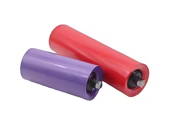
Another mistake is evaluating only the finished roller without understanding how it is produced. Two rollers may appear visually similar while being manufactured through very different levels of process control.
Tube cutting accuracy, shaft machining, bearing housing positioning, double-end assembly, welding, and inspection all influence repeatability. For large production batches, these manufacturing controls become particularly important because dimensional variation can otherwise be repeated across many components.
Technical evaluation should therefore examine manufacturing capability as part of product quality rather than treat it as separate background information.
Common Mistake: Treating Every Conveyor Position the Same
A single conveyor can contain several distinct operating zones. The loaded carrying section, return path, loading point, and belt-guidance areas each expose rollers to different forces and environmental conditions.
Using one roller structure everywhere may simplify the specification, but it does not always reflect the mechanical requirements of the system. The roller function should first be identified, followed by dimensions, bearings, sealing, shaft geometry, and material.
This position-based approach provides a stronger engineering foundation than selecting a generic roller and attempting to use it throughout the complete conveyor.
A Practical Technical Evaluation Framework
A useful evaluation can be organized around four connected areas: application, component structure, manufacturing process, and quality control.
| Evaluation Area | Questions to Confirm |
|---|---|
| Conveyor application | Belt width, position, load, material, environment |
| Roller structure | Diameter, length, shaft, bearing, seal, material |
| Manufacturing | Tube cutting, shaft machining, assembly, welding |
| Quality control | Drawings, staged inspection, final checks |
| Repeat production | Machine settings, fixtures, documented specifications |
| Standards | CEMA, ISO, GB, JIS, DIN where applicable |
Reviewing these areas together provides a clearer picture of whether a roller configuration can be manufactured consistently for the intended conveyor.
Why Technical Communication Matters
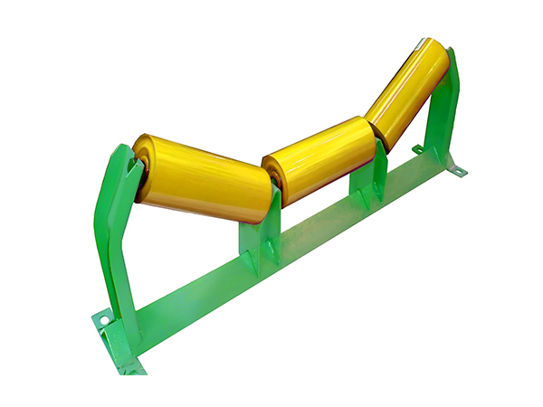
Many roller problems originate not from manufacturing failure but from incomplete information at the specification stage. If shaft-end geometry, conveyor position, or sealing environment is unclear, a technically sound component may still be unsuitable for the actual installation.
Effective communication should therefore focus on engineering information. Drawings, photographs, operating conditions, belt width, roller position, and existing component dimensions create a much clearer technical basis than a short product name alone.
This also improves repeatability because future production can refer to the same documented information instead of reconstructing the specification from memory.
Conclusion
Evaluating conveyor rollers suppliers requires more than checking whether they can produce a roller of a particular diameter and length. The finished component depends on the relationship between the tube, shaft, bearings, bearing housings, seals, surface treatment, installation geometry, and conveyor environment.
Manufacturing capability is equally important. Controlled tube preparation, shaft machining, assembly, welding, first-piece verification, and staged inspection provide the foundation for consistent production across larger batches.
The strongest technical evaluation therefore combines application requirements with component design and process capability. When drawings, materials, bearings, seals, manufacturing methods, standards, and inspection requirements are considered together, it becomes easier to define conveyor rollers that match the real operating conditions of an industrial belt system.
FAQ
What should be checked when evaluating conveyor rollers suppliers?
A technical evaluation should cover roller diameter and length, shaft geometry, bearings, bearing housings, seals, tube and shaft materials, surface treatment, manufacturing processes, inspection methods, applicable standards, and experience with the intended conveyor environment. These factors determine whether the complete roller matches the application.
Why should conveyor roller specifications include shaft details?
The shaft connects the roller assembly with the conveyor frame and provides the central reference for bearings and internal components. Its diameter, overall length, flats, grooves, and other end features influence installation accuracy. Correct shaft information therefore helps ensure that repeated rollers fit the same conveyor structure consistently.
How can roller suppliers maintain consistency across production batches?
Batch consistency depends on controlled drawings, raw materials, machine settings, tooling, fixtures, tube preparation, shaft machining, bearing assembly, welding, and staged inspection. First-piece checks after specification changes are especially useful because they verify the setup before the same conditions are repeated across a larger production run.
Why are seals important when specifying industrial conveyor rollers?
Seals help protect the bearing chamber from dust, moisture, and other contaminants entering around the roller ends. Their structure needs to match the shaft, bearing housing, bearing, and roller design. Harsh mining, quarrying, and cement environments make correct seal selection particularly important for the complete internal assembly.
What technical information should be prepared for a conveyor roller project?
Useful information includes belt width, roller position, roller diameter and length, shaft dimensions and end geometry, bearing and seal requirements, tube and shaft materials, surface treatment, conveyed material, environmental conditions, idler arrangement, and the applicable CEMA, ISO, DIN, JIS, or GB reference.
 English
 French
 Spanish