
Table of Contents
Introduction
Knowing how to cut metal pipes accurately is an important part of conveyor roller manufacturing. The roller shell normally begins as a length of steel tube, and the quality of the first cutting operation affects many of the processes that follow. If tube length varies, the two cut faces are not sufficiently parallel, or excessive burrs remain around the edge, later tube-end machining and roller assembly can become more difficult to control.
For repeated production, pipe cutting should therefore be treated as a precision manufacturing process rather than a simple separation operation. Material feeding, length positioning, workpiece clamping, cutting movement, tool condition, and finished-part inspection all influence the final result.
Automatic equipment can organize these functions into a controlled sequence. In conveyor roller production, a particularly useful configuration keeps the tube stationary while the cutting tool rotates around or relative to the workpiece. Combined with servo-controlled feeding and PLC-based operation, this approach can support repeated straight cuts across batches of roller tubes.
This guide explains how to cut metal pipes for conveyor roller manufacturing, which factors influence cutting accuracy, how automatic cutting systems work, and what should be checked before the tube moves to the next machining stage.
Why Metal Pipe Cutting Matters in Roller Manufacturing
The steel tube forms the outer shell of many conveyor rollers. Before bearing housings, shafts, seals, and related components can be assembled, the tube must first be prepared to the required dimensions.
This makes cutting one of the earliest opportunities to establish dimensional consistency.
If the tube is too long or too short, the finished roller may no longer correspond to its intended specification. If the two cut faces are not sufficiently parallel, later end machining may need to remove additional material. Irregular burrs can also interfere with handling or subsequent machining.
The effect of cutting quality therefore extends beyond the cutting station itself. A stable tube preparation process provides more predictable workpieces for double-end machining, bearing housing preparation, welding, and final assembly.
For this reason, manufacturers considering how to cut metal pipes should evaluate not only whether the machine can separate the tube, but also whether it can repeatedly produce workpieces suitable for the next manufacturing operation.
How to Cut Metal Pipes in a Controlled Production Process
Industrial pipe cutting can involve several methods depending on the required profile, material, wall thickness, and downstream operation. The general concept of pipe cutting includes both straight separation and more complex profiling processes.
For conveyor roller shells, the requirement is usually much more focused: produce a straight tube section at a controlled length with suitable end-face quality for subsequent manufacturing.
A typical automated process follows this sequence:
| Process Stage | Main Function | Why It Matters |
|---|---|---|
| Raw tube loading | Introduces tube material | Establishes continuous material flow |
| Feeding | Moves tube to required position | Determines finished length |
| Positioning | Stops tube at programmed point | Supports dimensional repeatability |
| Clamping | Holds tube securely | Prevents unwanted movement |
| Cutting | Separates the required section | Creates roller shell blank |
| Tool return | Resets cutting mechanism | Prepares next cycle |
| Material advance | Feeds next tube section | Supports repeated production |
| Inspection | Checks length and cut faces | Confirms process stability |
Each step influences the next. Precise cutting cannot be maintained if feeding varies, while accurate feeding provides limited benefit if the tube moves during the actual cutting operation.
The most stable production process therefore controls feeding, positioning, clamping, and cutting as one coordinated sequence.
Start With the Correct Tube Specification
Before setting cutting parameters, the raw tube itself should be checked against the roller specification.
Important factors include outside diameter, wall thickness, material, straightness, raw stock length, and the finished section length required for the roller shell.
Tube variation can affect how the workpiece behaves during feeding and clamping. A tube with significant straightness variation may not move through supports in the same way as a consistently straight workpiece. Wall thickness and material characteristics can also influence the cutting load and tool behavior.
Manufacturers should therefore define the acceptable raw material condition before relying on machine settings alone.
When the incoming tube remains within a consistent specification range, the automatic cutting system has a much stronger foundation for producing repeatable finished sections.
Accurate Feeding Comes Before Accurate Cutting
One of the most important principles when considering how to cut metal pipes accurately is that the finished length is established before the cutting tool enters the material.
A feeding system moves the tube into the required position. If this movement varies from one cycle to another, finished tube length will also vary even if the cutting mechanism itself performs perfectly.
Servo-controlled feeding is useful in repetitive production because the movement can be programmed according to a defined target position. Ball screws and linear guides can further support controlled material movement by providing a stable mechanical path.
In an automatic pipe cutting system, PLC-based operation can coordinate length setting, feeding, positioning, and cutting after the required production data has been entered.
This makes the feeding stage part of the overall machining cycle instead of a separate manual measuring operation.
Why the Pipe Can Remain Stationary During Cutting
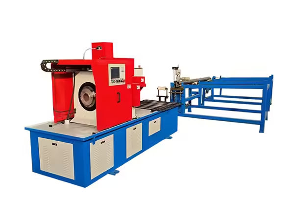
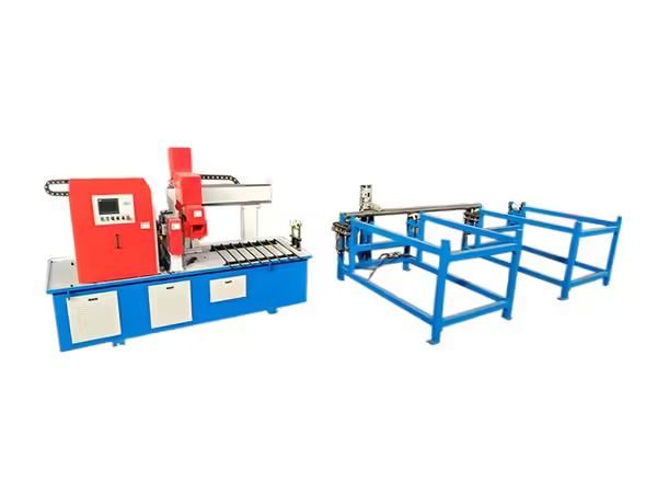
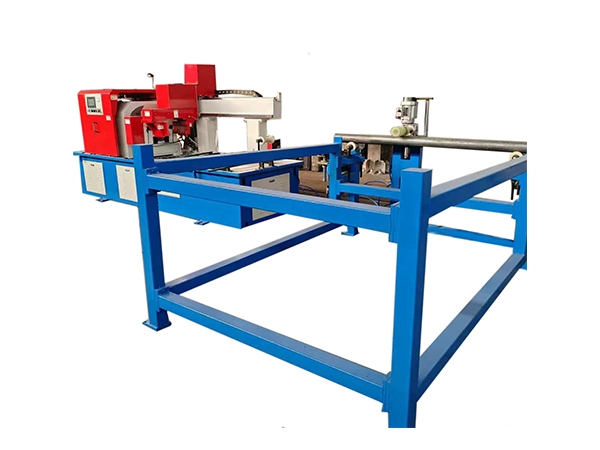
There are several possible machine arrangements for tube cutting. In the configuration used by Terok’s automatic pipe cutting equipment, the workpiece remains stationary while the cutting tool rotates.
This structure is particularly relevant to roller production because the workpiece may be relatively long. Rotating an entire long tube can create additional requirements for support, balance, and surrounding space.
Keeping the tube stationary allows the machine to control cutting movement around a fixed workpiece. Once the pipe has been fed to the required position and clamped, the cutting mechanism can perform its cycle without requiring the complete tube to rotate.
This can also simplify material support because the raw tube remains aligned with the feeding direction throughout the process.
The important point is not that one cutting arrangement is universally suitable for every pipe. The machine structure should correspond to the type of straight cutting required by the roller production process.
Clamping Prevents Position Loss During the Cut
Accurate feeding becomes ineffective if the workpiece moves when cutting begins. Clamping is therefore a critical link between positioning and material separation.
The clamp must hold the tube securely enough to resist cutting forces while avoiding unnecessary deformation of the workpiece.
Hydraulic clamping can provide a controlled and repeatable holding action during batch production. Once the tube reaches its programmed position, the clamp stabilizes it before the cutting tool engages.
Clamping consistency matters particularly when processing repeated sections from long tube stock. Every new cycle depends on the relationship between feed position and cutting location remaining stable.
Operators should also inspect clamping surfaces regularly. Wear, contamination, or incorrect adjustment can gradually change how the tube is positioned even when the control settings remain unchanged.
Tool Condition Directly Affects Cut Quality
The cutting tool is the component directly interacting with the metal, so its condition has an immediate influence on the finished surface.
As a tool wears, cutting behavior can change. Burr formation may increase, the cutting load can become less stable, and the end face may no longer maintain the same quality observed with a correctly maintained tool.
Tool inspection should therefore be part of routine production management rather than something performed only after a visible problem appears.
The appropriate inspection interval depends on material, wall thickness, production frequency, cutting parameters, and the tooling configuration being used.
A useful approach is to monitor the finished workpiece. Changes in burr condition, surface appearance, cutting behavior, or cycle consistency can indicate that tooling should be checked before the variation becomes more significant.
How to Control Metal Pipe Cutting Length
Length control combines machine positioning with process verification.
The operator first establishes the required finished length through the control system. The feeding mechanism then advances the material to the programmed position before each cutting cycle.
For repetitive roller production, this removes the need to manually measure every tube blank individually.
However, programmed dimensions should still be verified. The first finished sections after a setup change should be measured before a complete production batch proceeds.
Periodic checks during production can then confirm that feeding, clamping, and cutting continue to produce the expected result.
For the CNZDQ220 machine currently shown on the website, the stated cutting-length range is 300–2200 mm, with a listed cutting-length error of no more than 0.2 mm. These parameters illustrate the importance of matching machine capability with the roller shell dimensions being produced.
End-Face Parallelism Matters After Cutting
Finished tube length is not the only dimensional factor that matters. The relationship between the two cut faces can influence downstream processing as well.
If an end face is significantly angled relative to the tube axis, the effective length can vary around the circumference. Later machining may then require additional material removal to establish a suitable reference face.
For roller manufacturing, good end-face condition creates a more predictable blank for subsequent processing.
The CNZDQ220 specification lists a parallelism error between the two cut sections of no more than 0.2 mm. This type of parameter is especially relevant when the cut tube will later enter a controlled machining and assembly process.
Manufacturers should therefore include both overall length and end-face condition in their cutting inspection procedure.
Reducing Burrs Before the Next Process
Burrs are raised or irregular material remaining around a cut edge. Some burr formation is common in mechanical cutting, but excessive burrs can affect handling and downstream processing.
A smooth cutting process depends on several factors, including tool condition, cutting movement, material characteristics, clamping stability, and machine setup.
Rather than relying entirely on secondary deburring, manufacturers should first try to maintain a cutting process that produces a suitable edge consistently.
Where additional edge preparation is required, it should be incorporated deliberately into the manufacturing sequence.
This is important in roller production because the cut tube may proceed directly to end machining or other operations. Stable edge condition reduces variation in how each workpiece enters the next stage.
Steel Pipe Cutting for Conveyor Roller Shells
Steel pipes used as roller shells need to be processed according to the dimensions required by the specific roller design.
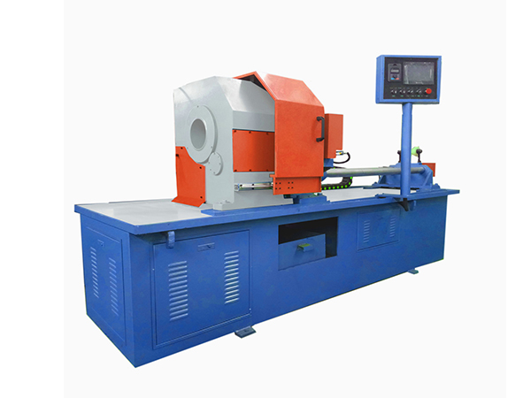
A round steel pipe cutting machine can combine automatic feeding, hydraulic clamping, PLC-controlled movement, and cutting into one repeated production sequence. The workpiece remains stationary while the cutting tool performs the separation operation.
This structure is suited to repeated straight cutting of round tube material.
For roller manufacturing, it is useful to consider cutting as the beginning of a chain of controlled processes:
Steel tube preparation → cutting → tube-end machining → component assembly → welding or additional processing → inspection
Problems created during the first stage can continue through every process that follows, which is why tube preparation deserves the same attention as later precision machining operations.
How Wall Thickness Influences Cutting
Tube wall thickness affects the amount of material the cutting tool must remove during each cycle.
A thicker wall generally changes the cutting load compared with a thinner tube of the same outside diameter. Machine setup and tool condition should therefore correspond to the material actually being processed.
The CNZDQ220 specification currently lists a tube wall thickness range of 3–20 mm. This should be treated as part of the machine’s defined working range rather than assuming that every tube with the correct outside diameter will behave identically.
Manufacturers should review diameter, wall thickness, material, and finished length together when establishing the cutting process.
This helps prevent a common mistake: configuring the machine according to outside diameter alone while overlooking the amount of material the tool must actually cut.
How Tube Diameter Affects Machine Setup
Tube diameter influences workpiece support, clamping, cutting position, and tooling engagement.
The cutting machine must accommodate the outside diameter while holding the tube securely along the intended centerline. When manufacturers process several roller diameters, machine adjustment should be performed systematically between specifications.
For the CNZDQ220 configuration, the stated pipe diameter range is Φ89–219 mm.
Before production begins, the operator should confirm that the tube falls within the machine’s intended working range and that supports and clamps have been adjusted correctly.
The first completed piece after changing diameter should receive additional inspection so that positioning and cut condition can be verified before repeated production continues.
PLC Control Helps Coordinate the Cutting Sequence
PLC control is useful because automatic cutting depends on several actions occurring in the correct order.
The tube should first move to its target position. It must then be stabilized before cutting begins. The cutting mechanism should complete its movement before the machine releases the workpiece and feeds the next section.
A programmable controller can coordinate this sequence consistently.
For the operator, this means production settings can be established around the required tube length and machine cycle instead of manually commanding every individual movement.
The PLC does not determine cutting quality by itself. Mechanical condition, servo positioning, hydraulic clamping, tooling, raw material, and operator setup still influence the process.
Its role is to provide a repeatable control structure connecting these elements.
Servo Feeding and Positioning Repeatability
Servo systems allow controlled motor movement according to programmed position commands.
In automatic tube cutting, this capability can be used to manage feed movement and tool movement. The feeding mechanism needs to advance the tube by the required distance repeatedly, while the cutting mechanism must perform a defined cycle.
Repeatability is particularly important when many identical roller shells are produced from long stock.
Instead of treating each tube section as a separate manual operation, servo positioning allows the machine to repeat the same commanded movement from one cycle to the next.
For manufacturers, the main production benefit is not automation by itself. It is the ability to establish a cutting process that can be reproduced across a batch while still being checked against actual finished dimensions.
Common Problems When Cutting Metal Pipes
Even with automatic equipment, several process conditions can lead to inconsistent results.
Inaccurate finished lengths may originate from feeding or positioning variation. Uneven cut faces can be related to tool condition, workpiece movement, machine alignment, or improper setup. Increased burr formation may indicate tool wear or unsuitable cutting conditions.
Another issue is changing raw material condition. If one batch of tube differs noticeably in straightness, wall thickness, or material behavior, the established machine setup may no longer produce exactly the same result.
Troubleshooting should therefore follow the production sequence:
First confirm raw material.
Then verify feeding position.
Check clamping.
Inspect the cutting tool.
Review machine movement.
Finally measure the finished tube.
Following this order makes it easier to identify where variation first enters the process.
Inspection After Metal Pipe Cutting
Inspection should occur before the tube moves into downstream machining.
For roller shell production, useful checks include finished length, end-face condition, parallelism, burr condition, visible deformation, and general consistency between workpieces.
The first workpiece after a machine setup or specification change deserves particular attention. Once the process has been confirmed, periodic inspection can be used to monitor continued production.
Measurement results can also help identify gradual process changes.
If tube length begins drifting while surface quality remains stable, the feeding and positioning system may deserve closer attention. If dimensional results remain consistent but burrs increase, the cutting tool may be the more likely area to inspect.
Using inspection as process feedback is more effective than treating it only as a final acceptance step.
Connecting Pipe Cutting With Tube-End Machining
The quality of the cut tube affects the next machine in the production sequence.
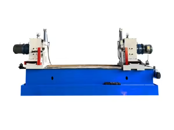
Roller tubes may later require double-end machining so bearing housings or related components can be positioned correctly. A tube blank with controlled length and predictable end surfaces provides a more stable starting point for this operation.
This illustrates an important principle in roller production: each machine should prepare the workpiece for the machine that follows.
The objective of pipe cutting is therefore not simply to create separate lengths of steel tube. It is to produce roller shell blanks that can move efficiently into the next defined manufacturing stage.
When cutting and end machining are planned together, the overall process becomes easier to control.
How to Improve Repeatability in Batch Pipe Cutting
Repeatability comes from controlling several small variables at the same time.
Raw tube specifications should remain consistent. Machine supports and clamping points should be correctly adjusted. Feed positions should be verified after setup. Cutting tools should remain within suitable operating condition, and finished dimensions should be checked at defined intervals.
Operators should also use consistent setup procedures when switching between tube specifications.
Recording validated settings for frequently processed diameters and lengths can make future production runs easier to establish. These records can include feed settings, machine configuration, inspection points, and tooling information.
The result is a process based on defined manufacturing conditions rather than repeated trial adjustment.
Choosing the Appropriate Cutting Process for Roller Tubes
The appropriate cutting process should reflect the geometry required from the finished part.
Conveyor roller shells generally require controlled straight cuts rather than complex profiles. This makes accurate feeding, clamping, and perpendicular separation particularly important.
Manufacturers should evaluate the required tube diameter, wall thickness, finished length, material, production frequency, and downstream machining requirements before establishing the process.
The surrounding manufacturing line should also be considered. A cutting machine that produces workpieces faster than subsequent tube-end processing can handle may simply move the production bottleneck to the next operation.
Balanced production is therefore more useful than maximizing one isolated cutting stage.
Maintenance for Consistent Metal Pipe Cutting
Machine condition has a direct influence on repeated cutting performance.
Routine maintenance should include the feeding mechanism, servo system, ball screws, linear guides, clamping components, hydraulic system, cutting mechanism, sensors, and electrical control elements according to the equipment’s operating requirements.
Tool inspection should receive particular attention because the cutting edge directly influences the finished workpiece.
Material chips and debris should also be removed from areas where they can affect workpiece positioning or machine movement.
Operators should monitor changes in machine sound, movement, cutting behavior, and finished-part condition. Gradual changes can provide early indications that inspection is required before dimensional variation becomes significant.
Conclusion
Understanding how to cut metal pipes accurately requires looking beyond the cutting tool itself. Reliable conveyor roller tube preparation depends on the combined control of raw material condition, feeding, positioning, clamping, cutting movement, tooling, machine setup, and inspection.
For repeated roller production, an automatic system can organize these functions into a defined cycle. Servo-controlled feeding helps establish tube length, hydraulic clamping stabilizes the workpiece, PLC control coordinates machine actions, and a rotating-tool configuration allows the long tube to remain stationary during cutting.
Finished length, end-face parallelism, burr condition, and consistency between workpieces should all be checked before the tube proceeds to later machining.
When pipe cutting is treated as the first precision stage of conveyor roller manufacturing rather than a simple material-separation operation, downstream tube machining, assembly, and inspection can begin from a much more stable workpiece condition.
FAQ
How to cut metal pipes accurately for conveyor roller production?
Accurate cutting requires controlled material feeding, stable positioning, secure clamping, suitable tooling, consistent machine movement, and dimensional inspection. The finished tube should also meet the end-face requirements needed for subsequent roller machining.
Why can the tube remain stationary during automatic cutting?
A stationary-workpiece design allows the cutting tool to perform the cutting movement while the long tube remains supported along the feeding direction. This can simplify handling of long roller tube material.
What dimensions should be checked after cutting a roller tube?
Important checks can include overall tube length, end-face condition, parallelism between cut sections, burr condition, and any visible deformation that could affect downstream machining.
How does servo feeding improve tube cutting?
Servo feeding provides programmable position control, allowing the machine to repeat the required material advance for each cutting cycle. Actual finished dimensions should still be verified during production.
Why should pipe cutting be coordinated with later roller machining?
The cut tube becomes the starting workpiece for later operations. Length variation, uneven end faces, or poor edge condition can create additional variation during tube-end machining, assembly, and other roller manufacturing stages.
 English
  French
  Spanish