

Table of Contents
Introduction
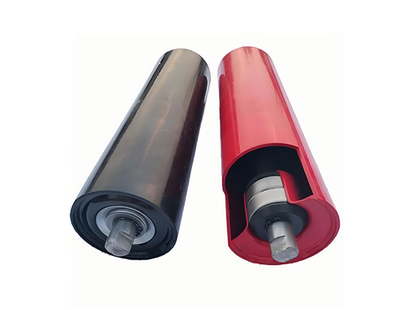
Conveyor pulleys are easy to recognize but surprisingly easy to specify incorrectly. A pulley may have the correct face width and appear mechanically robust, yet still create problems if its diameter, shaft design, lagging, bearing arrangement, alignment, or operating position does not match the conveyor.
Unlike idler rollers, which mainly support the belt along its route, conveyor pulleys interact more directly with belt direction, tension, traction, and power transmission. A drive pulley may need to transfer torque into the belt, while a tail or bend pulley primarily redirects and supports it. That difference changes how each component should be engineered.
If you are selecting pulleys for a new conveyor or replacing existing components, the most useful starting point is not a catalogue dimension. It is the mechanical role of the pulley inside the complete system.
Key points in this article:
- Identify pulley function before choosing dimensions.
- Do not treat head, tail, bend, snub, and take-up pulleys as interchangeable.
- Match pulley diameter to belt construction and operating conditions.
- Evaluate lagging according to traction and contamination conditions.
- Check shaft design together with belt tension and bearing locations.
- Treat pulley alignment as a conveyor-system issue.
- Review manufacturing accuracy, runout, and balance before installation.
- Diagnose repeated pulley problems instead of simply replacing components.
The following seven mistakes explain where pulley selection commonly goes wrong and how a more systematic engineering approach can improve belt stability.
Mistake 1: Treating All Conveyor Pulleys as the Same Component
One of the most basic mistakes is specifying pulleys primarily by diameter and face width without first identifying their function.
A conveyor belt changes direction and interacts with several rotating components throughout a typical conveyor system. Each pulley position can create a different combination of belt tension, wrap, traction, load, and environmental exposure.
Drive or Head Pulley
The drive pulley transfers rotational force from the drive system to the belt.
Its design therefore needs to consider:
- Belt tension
- Required traction
- Belt wrap
- Pulley diameter
- Shaft loading
- Lagging
- Drive connection
- Bearing arrangement
Because torque is transmitted at this location, the drive pulley should not be evaluated in exactly the same way as a non-driven pulley.
Tail Pulley
The tail pulley is normally positioned toward the opposite end of the conveyor and redirects the belt back toward the carrying section.
Its responsibilities can include:
- Belt redirection
- Supporting belt entry into the carrying run
- Maintaining suitable geometry
- Working with the conveyor tensioning arrangement
- Operating near loading or material-return areas
More detailed differences between a head pulley and tail pulley are useful when determining why these two positions require different engineering considerations.
Snub Pulley
A snub pulley changes the belt path near another pulley.
One common purpose is increasing belt wrap around the drive pulley. Greater contact between belt and drive surface can influence traction, but the complete drive geometry still needs to be evaluated.
Bend Pulley
A bend pulley redirects the belt through the conveyor.
Its main requirement is not torque transmission but controlled belt redirection under the operating tension present at that position.
Take-Up Pulley
A take-up pulley forms part of a belt-tensioning arrangement.
Because its position may move as the tensioning system compensates for changes in belt condition, its shaft, bearing, mounting, and travel arrangement need to suit that function.
The first specification question should therefore be:
“What mechanical job does this pulley perform?”
Only after that should dimensions be finalized.
Mistake 2: Choosing Pulley Diameter Without Considering the Belt
Pulley diameter is one of the most frequently compared specifications for conveyor pulleys.
However, diameter does more than determine whether the pulley physically fits into the frame.
As a belt bends around a pulley, the belt experiences repeated flexing. The relationship between pulley diameter and belt construction therefore matters.
Smaller is not automatically more efficient
A smaller pulley can reduce the space required by the conveyor layout, but compact geometry should not be considered independently of belt requirements.
The suitable diameter depends on factors such as:
- Belt construction
- Belt thickness
- Belt tension
- Pulley position
- Conveyor speed
- Drive arrangement
- Belt manufacturer requirements
A belt that is repeatedly forced around an unsuitable diameter may experience a different flexing condition from the one intended in its design.
Larger is not automatically better either
Increasing diameter without engineering justification can affect:
- Conveyor geometry
- Shaft requirements
- Bearing arrangement
- Belt path
- Component mass
- Drive configuration
The objective is not to specify the largest possible conveyor pulleys.
It is to determine a diameter appropriate for the belt and the function of that pulley.
Drive and non-drive pulleys may need different consideration
The drive pulley combines belt bending with torque transmission.
A bend pulley may primarily redirect the belt.
Although both can appear similar externally, their operating conditions differ.
This is why pulley diameter should be selected according to position rather than standardized across the conveyor simply for convenience.
Mistake 3: Selecting Lagging Without Defining the Traction Problem
Lagging is the surface layer applied to certain conveyor pulleys to modify the interface between the pulley and belt.
It can improve traction, protect the pulley shell, or provide surface characteristics suitable for a particular operating environment.
A frequent mistake is assuming that more aggressive lagging is always better.
Start with the reason lagging is needed
Ask what problem the surface is expected to solve.
Possible requirements include:
- Improving belt-to-pulley traction
- Managing wet operating conditions
- Protecting the pulley surface
- Supporting consistent belt contact
- Handling abrasive contamination
Different pulley positions may not require the same surface.
Drive pulley lagging
Traction is especially important at the drive pulley because rotational force must be transferred into belt movement.
The effectiveness of this interface depends on more than the lagging material alone.
It can also be influenced by:
Belt tension + belt wrap + surface condition + contamination + pulley geometry.
Therefore, replacing lagging without examining the complete drive condition may fail to solve repeated belt slip.
Non-drive pulley surfaces
Tail, bend, and take-up pulleys do not automatically require the same surface configuration as the drive pulley.
Their operating conditions should be evaluated separately.
For example, a pulley exposed to material carryback may have different surface-management requirements from a drive pulley operating in a relatively controlled area.
More traction does not solve poor alignment
Lagging should not be used as a substitute for correct conveyor geometry.
If the belt is tracking incorrectly because of frame alignment, loading position, pulley alignment, or another mechanical problem, changing the surface alone may leave the original cause unchanged.
Mistake 4: Underestimating Shaft and Bearing Loads
The pulley shell is visually dominant, but the shaft and bearings transfer the pulley loads into the surrounding structure.
They deserve equal engineering attention.
A conveyor pulley shaft may be subjected to forces associated with:
- Belt tension
- Pulley weight
- Drive torque
- Bearing spacing
- Hub location
- Belt loading
- Shaft geometry
These forces should be considered together.
Shaft diameter alone does not describe shaft capability
Two shafts with the same diameter may behave differently depending on:
- Material
- Unsupported length
- Bearing spacing
- Pulley width
- Hub position
- Keyway or connection geometry
- Changes in shaft section
The shaft needs to maintain suitable stiffness and strength under its real operating condition.
Bearing location changes shaft behavior
Imagine the pulley shell located between two bearings.
Increasing the distance between the pulley and bearing can change shaft bending behavior. This means overall conveyor layout influences shaft design.
The pulley cannot be engineered independently from its support arrangement.
Drive shafts require additional attention
A drive pulley shaft must also interact with the drive system.
Depending on the configuration, this may involve:
- Couplings
- Gearboxes
- Keyed connections
- Locking assemblies
- Other torque-transfer components
Alignment between these elements matters because the shaft is not simply holding the pulley in position; it is also part of the power transmission path.
Mistake 5: Ignoring Pulley Runout and Manufacturing Accuracy
A conveyor pulley can meet nominal diameter and width specifications while still producing unstable rotation.
Manufacturing accuracy determines how closely the actual rotating component follows its intended geometry.
What is pulley runout?
Runout describes variation in the rotating pulley surface relative to its rotational axis.
It can be influenced by:
- Shell geometry
- End-disc positioning
- Hub alignment
- Shaft machining
- Welding distortion
- Final assembly
Excessive variation can create repeated changes in belt contact as the pulley rotates.
Welding needs geometric control
Many conveyor pulleys rely on welded assemblies involving the shell, end discs, hubs, or related structural components.
Welding introduces heat.
Without suitable fixture control and production sequencing, this can influence finished geometry.
For this reason, good pulley manufacturing needs to control both joint integrity and dimensional stability.
Shaft machining matters to the final assembly
Bearing seats, drive connections, keyways, shoulders, and other shaft features need to maintain their intended relationship.
A pulley shell manufactured accurately cannot compensate for an incorrectly positioned shaft feature.
Manufacturing repeatability matters for replacement pulleys
A single acceptable pulley proves individual capability.
Consistent production requires multiple pulleys to maintain the same critical dimensions and installation interfaces.
This is particularly important where conveyor operators depend on interchangeable replacement components.
A practical inspection plan can include:
| Inspection Area | Why It Matters |
|---|---|
| Pulley diameter | Confirms belt interface geometry |
| Face width | Confirms belt support area |
| Shaft dimensions | Supports installation compatibility |
| Bearing seats | Influences bearing alignment |
| Hub position | Influences shaft-to-shell geometry |
| Surface runout | Indicates rotating geometry |
| Lagging condition | Influences belt interface |
| Weld condition | Supports structural integrity |
| Overall alignment | Helps reduce installation problems |
Not every project needs the same inspection method, but the characteristics that influence belt interaction and installation should be clearly defined.
Mistake 6: Treating Pulley Alignment as an Isolated Component Problem
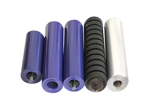
Some pulley problems are not pulley problems at all.
They are conveyor geometry problems that become visible at the pulley.
If a belt continually moves sideways, changing the pulley without examining the surrounding conveyor may simply repeat the same failure pattern.
Pulley axis alignment
The pulley axis needs the intended relationship with the conveyor centerline and belt path.
Incorrect alignment can influence:
- Belt tracking
- Edge contact
- Belt position
- Bearing loading
- Surface wear
A well-manufactured pulley installed in a distorted supporting structure may still operate poorly.
Check the structure before blaming the component
Repeated belt deviation near one pulley should prompt inspection of:
- Pulley mounting points
- Bearing housings
- Supporting frame
- Nearby idlers
- Belt condition
- Material loading
- Material buildup
- Adjacent pulley alignment
Looking at the surrounding structure often provides more useful information than repeatedly adjusting one component.
Belt loading influences tracking
Material should enter the belt in a controlled manner.
Strongly off-center loading can influence how the belt moves through the conveyor. This may appear later as pulley or tracking trouble even though the original disturbance began at the loading zone.
Crowned pulleys are not a universal tracking solution
A crowned pulley has a slightly different diameter profile across its face and may assist tracking in appropriate systems.
However, crowning should not be applied blindly.
Its suitability depends on conveyor design, belt behavior, pulley position, and other system characteristics.
Fundamental mechanical alignment should still be established first.
Mistake 7: Replacing Conveyor Pulleys Without Diagnosing the Failure
When a pulley begins causing operational problems, replacement can restore the conveyor temporarily.
But if the original cause remains, the new component may encounter the same conditions.
A stronger maintenance approach asks why the pulley deteriorated.
Lagging wear
If lagging wears unusually quickly, investigate:
- Belt slip
- Contamination
- Material buildup
- Belt tension
- Incorrect surface selection
- Misalignment
The worn lagging may be the symptom rather than the root cause.
Bearing problems
Bearing deterioration can be associated with:
- Contamination
- Alignment
- Lubrication condition
- Shaft geometry
- Installation
- Unexpected loading
Repeated bearing problems at the same pulley position deserve system-level investigation.
Shaft or hub problems
Unusual vibration, movement, or connection wear may indicate issues involving:
- Shaft loading
- Coupling alignment
- Hub connection
- Drive alignment
- Bearing position
Replacing only the visibly damaged component may leave these underlying conditions unchanged.
Shell or structural damage
Shell deformation or structural damage can indicate abnormal loading, material buildup, or a mismatch between pulley construction and operating conditions.
This is why pulley inspection should include the operating environment rather than only the removed component.
Head, Tail, Snub, Bend, and Take-Up Conveyor Pulleys Compared
A functional comparison can make initial specification easier.
| Pulley Type | Main Role | Key Selection Focus |
|---|---|---|
| Drive/Head Pulley | Transfers drive force to belt | Traction, torque, shaft, lagging |
| Tail Pulley | Redirects belt at conveyor end | Alignment, contamination, geometry |
| Snub Pulley | Modifies belt path and wrap | Position, wrap geometry, belt tension |
| Bend Pulley | Redirects belt | Diameter, shaft load, belt tension |
| Take-Up Pulley | Works with tensioning system | Travel, tension, mounting, bearings |
The table also reveals why a request for “one standard pulley” can be incomplete.
Pulley function should be specified before detailed construction.
A Better Method for Specifying Conveyor Pulleys
Instead of beginning with dimensions, use an application sequence.
Step 1: Define pulley position
Identify whether the component is:
- Drive
- Tail
- Bend
- Snub
- Take-up
- Another specialized pulley
This establishes its mechanical purpose.
Step 2: Define the belt
Provide information about:
- Belt width
- Belt construction
- Belt thickness
- Operating tension
- Belt speed
- Manufacturer requirements
The belt and pulley work as one interface.
Step 3: Define conveyor loading
Understand:
- Material type
- Normal operating load
- Loading method
- Conveyor duty
- Start-stop behavior
These conditions affect the forces throughout the system.
Step 4: Define belt wrap and drive conditions
For drive applications, determine how much contact exists between the belt and pulley and what traction conditions are expected.
Snub pulley location may also influence this geometry.
Step 5: Define the environment
Record exposure to:
- Dust
- Moisture
- Abrasive material
- Material carryback
- Temperature variation
- Outdoor conditions
This information influences lagging, bearings, sealing, and surface protection.
Step 6: Define shaft and bearing arrangement
Prepare dimensions for:
- Shaft ends
- Bearing positions
- Drive connection
- Pulley face
- Mounting locations
Do not finalize the pulley without understanding how it will be supported.
Step 7: Define inspection requirements
Identify which characteristics are important for the application.
These may include:
- Dimensional accuracy
- Runout
- Shaft geometry
- Weld condition
- Lagging condition
- Assembly alignment
For complex replacement or project specifications, an application-specific technical review can also be based on drawings, pulley position, belt information, shaft geometry, and operating conditions rather than a basic diameter request alone.
How Conveyor Pulleys and Rollers Work Together
Pulleys and rollers should not be treated as unrelated conveyor components.
The pulleys define major belt-direction changes and, at the drive position, transmit motion. Idler rollers support the belt between those major points.
The belt therefore moves through a connected geometry:
Drive pulley
Carrying idlers
Terminal pulley
Return idlers
Additional bend or take-up pulleys
Drive pulley
A problem at one component can change how the belt interacts with the others.
Pulley alignment affects idler behavior
If a pulley introduces the belt into a conveyor section at an incorrect angle, downstream idlers may continually attempt to support a belt that is already moving off center.
Idler problems can appear as pulley problems
Conversely, poorly aligned idlers can gradually influence the belt path before it reaches a pulley.
This makes system-level inspection important.
Material buildup connects both systems
Carryback can accumulate around pulleys, rollers, and supporting structures.
The resulting change in contact conditions can influence tracking and component behavior.
For maintenance teams, separating the conveyor into isolated components can therefore hide the relationship between the actual causes of recurring problems.
A Practical Conveyor Pulley Evaluation Matrix
Before approving a pulley specification, review it against the operating condition.
| Evaluation Area | Question |
|---|---|
| Function | What does this pulley do in the conveyor? |
| Belt | Does the diameter suit the belt construction? |
| Load | What belt tension acts at this position? |
| Drive | Does the pulley transfer torque? |
| Wrap | What belt contact geometry is required? |
| Lagging | What traction or surface condition is needed? |
| Shaft | Does the shaft suit tension, torque, and bearing spacing? |
| Bearings | Are load and environmental conditions understood? |
| Environment | Is contamination likely? |
| Alignment | Can the pulley be installed on the correct axis? |
| Manufacturing | Are runout and critical dimensions controlled? |
| Maintenance | Can bearings, lagging, and nearby components be inspected? |
If several answers remain unknown, the pulley specification is probably not complete.
This method also helps prevent over-specification. Not every conveyor pulley needs every available feature; the engineering should reflect the actual duty.
Signs That a Conveyor Pulley Specification Needs Review

Several operating symptoms can indicate that the current pulley or surrounding system needs further investigation.
Repeated belt slip
Check:
- Lagging
- Belt condition
- Belt tension
- Wrap
- Contamination
- Drive conditions
Do not assume lagging replacement is automatically the solution.
Persistent belt tracking problems
Review:
- Pulley alignment
- Frame alignment
- Loading position
- Idlers
- Material buildup
- Belt condition
Unusual vibration
Possible areas for inspection include:
- Pulley runout
- Shaft alignment
- Bearings
- Coupling
- Structural mounting
- Material buildup
Localized lagging wear
Uneven wear across the pulley face can provide useful information about belt contact and alignment.
Repeated bearing problems
If bearings at the same position deteriorate repeatedly, investigate loading, contamination, shaft alignment, installation, and support geometry.
These symptoms should be treated as diagnostic evidence.
Conclusion
Conveyor pulleys are central to the geometry and mechanical behavior of a belt conveyor.
The drive pulley transfers motion. The tail pulley redirects the belt. Snub pulleys modify belt wrap and direction. Bend pulleys guide the belt through the conveyor layout. Take-up pulleys interact with the tensioning system.
Because these functions differ, pulley selection should begin with position rather than external dimensions.
Diameter needs to suit the belt. Lagging needs to address an actual traction or surface condition. Shaft and bearings need to match belt tension, torque, and support geometry. Manufacturing needs to control shaft features, assembly relationships, welding distortion, and rotating geometry.
Alignment is equally important.
Even correctly manufactured conveyor pulleys can operate poorly when installed into an incorrectly aligned system. Repeated belt slip, tracking problems, vibration, lagging wear, and bearing deterioration should therefore trigger a review of the complete conveyor rather than automatic component replacement.
The most useful specification question is not:
“What size pulley do I need?”
It is:
“What mechanical function does this pulley perform, and what belt forces, geometry, environment, and operating conditions must it control?”
Answering that question first provides a much stronger foundation for selecting conveyor pulleys that integrate properly with the entire belt system.
FAQ
What are conveyor pulleys used for?
Conveyor pulleys guide, redirect, tension, or drive a conveyor belt depending on their position. Drive pulleys transmit motion to the belt, while tail, bend, snub, and take-up pulleys perform different belt-routing and tension-related functions within the conveyor system.
How do I choose the correct conveyor pulleys?
Start with pulley function, belt width, belt construction, tension, speed, wrap, and operating environment. Then determine pulley diameter, face width, shaft design, bearings, lagging, mounting dimensions, and manufacturing requirements based on the actual position in the conveyor.
What is the difference between head and tail conveyor pulleys?
A head pulley is commonly associated with the drive end and may transfer torque into the belt. A tail pulley is located toward the opposite end and redirects the returning belt. Their tension, traction, contamination, shaft, and surface requirements can therefore differ.
Why is lagging used on conveyor pulleys?
Pulley lagging modifies the contact surface between the belt and pulley. Depending on the application, it can improve traction or protect the pulley surface. Lagging should be selected according to pulley function, belt conditions, contamination, and required surface behavior.
What causes conveyor pulley alignment problems?
Pulley alignment problems can be related to mounting position, bearing supports, frame geometry, installation errors, structural movement, material buildup, or surrounding conveyor components. Belt loading and idler alignment should also be checked when tracking problems repeatedly occur.
 English
 French
 Spanish