

Table of Contents
Introduction
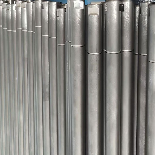
Metal conveyor rollers are widely used in industrial conveying systems because they combine structural strength, dimensional stability, and compatibility with a broad range of loads and operating environments. Their performance, however, depends on much more than the metal tube itself. Shell thickness, shaft geometry, bearing arrangement, sealing, surface condition, roller spacing, alignment, and manufacturing accuracy all influence how the roller behaves after installation.
In a working conveyor, each roller becomes part of a larger mechanical system. The load carried by the belt or transported product is transferred through the roller shell, bearings, shaft, mounting structure, and surrounding frame. If one of these relationships is poorly matched, increasing the strength of another component does not necessarily solve the problem.
A well-designed metal roller therefore needs to balance several requirements at once. It must support the intended load without excessive deformation, rotate consistently, resist the surrounding environment, fit the conveyor structure accurately, and remain practical to inspect and replace over time.
For engineers and production teams, the useful question is not simply whether a roller is “heavy duty.” The more meaningful question is whether the complete roller construction matches the mechanical conditions at its actual installation position.
This article explains how metal conveyor rollers carry load, why shell and shaft design must be considered together, how bearings and seals affect rotation, where manufacturing accuracy matters, and what should be reviewed before selecting a roller configuration for long-term conveyor operation.
How Metal Conveyor Rollers Carry Load
A conveyor system transfers material through a sequence of mechanical components, but the way forces reach individual rollers depends on the conveyor design. In a belt conveyor, the belt distributes material load into carrying idlers. In a roller conveyor, the transported item may contact the rollers directly.
In both cases, the roller is not simply supporting weight vertically. Load is transferred through several interfaces.
The shell first receives contact from the belt or product. That force moves through the shell toward the bearing positions. Bearings transfer it into the shaft, while the shaft carries it into the conveyor bracket or frame.
The complete load path is therefore important.
A stronger shell cannot fully compensate for an undersized shaft. A large shaft cannot correct poor bearing alignment. High-capacity bearings cannot overcome unstable mounting geometry.
Reliable metal conveyor rollers are created when each part of this load path is designed around the same operating condition.
Load is rarely perfectly uniform
Material does not always remain centered on a conveyor belt, and unit loads do not always contact every supporting roller evenly. As a result, one section of a roller may experience greater loading than another.
Dynamic forces can also appear during loading, stopping, material impact, or changes in conveyor direction.
This is why roller specification should consider normal working conditions rather than relying only on a single maximum load figure.
Why Metal Is Commonly Used for Conveyor Rollers
Metal provides several characteristics that make it practical for industrial roller construction. It can provide relatively high stiffness, maintain dimensional geometry under load, and be manufactured into tubes and shafts with predictable dimensions.
For many conveyor applications, these characteristics make metal rollers suitable for continuous operation where the supporting components need to remain stable over repeated cycles.
However, the word “metal” does not define the complete roller.
Different metal grades, tube dimensions, surface treatments, shaft materials, and bearing arrangements can create very different operating characteristics.
A roller should therefore be specified as a complete assembly rather than simply described as a metal roller.
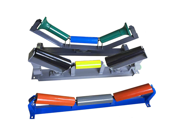
The site’s existing conveyor rollers illustrate how conveyor roller configurations can vary by dimensions, construction, idler arrangement, bearing requirements, and application rather than following one universal design.
Strength is only one selection factor
A stronger material may increase structural capability, but other properties still matter.
These can include:
- Surface condition
- Corrosion exposure
- Component mass
- Weldability
- Dimensional consistency
- Interaction with the conveyed material
- Maintenance environment
Material should solve the actual operating problem rather than simply maximize one mechanical property.
Shell Diameter and Wall Thickness Must Be Evaluated Together
The cylindrical shell is the visible working surface of metal conveyor rollers. Its diameter and wall thickness influence how the roller responds to load, but these two dimensions should be considered together with roller length and bearing position.
A longer roller experiences a different bending condition from a shorter roller with the same diameter.
Likewise, increasing shell diameter changes the roller geometry and may increase structural stiffness, but the benefit depends on the complete design.
Roller diameter influences several relationships
Diameter can affect:
- Shell rigidity
- Available internal space
- Bearing arrangement
- Rotational characteristics
- Belt or product contact
- Installation geometry
This means the largest possible diameter is not automatically the best option.
The appropriate diameter needs to fit the conveyor structure while providing suitable mechanical performance.
Wall thickness supports shell stability
The shell needs enough thickness to resist the loads applied between its bearing locations.
If the wall is too thin for the combination of roller length and operating load, the shell may deform more than intended.
However, excessive wall thickness can increase rotating mass without addressing other limiting components.
If bearing alignment or shaft stiffness is the real weakness, increasing shell thickness alone does not solve the complete problem.
A balanced roller design distributes capability across the shell, shaft, bearings, and mounting points.
Shaft Design Is Just as Important as the Roller Shell
The shaft provides the structural connection between the rotating roller and the stationary conveyor frame.
Because most of the roller is hidden inside the shell, shaft design is sometimes given less attention than external dimensions. In practice, it is one of the most important structural elements.
A shaft may include:
- Stepped diameters
- Flats
- Grooves
- Threads
- Slots
- Machined mounting ends
- Bearing surfaces
These features determine how the roller fits into the conveyor and how loads are transferred into the supporting structure.
Shaft-end geometry affects interchangeability
For replacement rollers, two components can share the same shell diameter and overall length while still being incompatible because their shaft ends differ.
Mounting geometry should therefore be defined precisely.
Important dimensions can include shaft diameter, mounting length, flat size, groove position, and other installation-related features.
Shaft stiffness influences roller alignment
A shaft that deflects excessively under load can change the relationship between bearings and the roller shell.
This can influence rotational geometry and bearing loading.
Shaft diameter therefore needs to be considered alongside:
- Roller length
- Applied load
- Bearing location
- Mounting spacing
- Shaft material
- End geometry
The roller shell and shaft should be treated as one structural system.
Bearings Control the Rotational Behavior of Metal Conveyor Rollers
A metal roller can be structurally strong and still perform poorly if the bearing system is unsuitable.
Bearings allow the shell to rotate around the shaft while transferring operating load. Their condition directly influences rotational resistance, noise, vibration, and long-term consistency.
Bearing selection begins with load and speed
The required bearing arrangement depends on several factors:
- Radial load
- Roller dimensions
- Shaft geometry
- Conveyor speed
- Operating duration
- Environmental contamination
- Installation alignment
A bearing that works well in one roller may not be suitable for another roller of different length, speed, or load.
Bearing position needs manufacturing accuracy
Both bearing locations should maintain the intended relationship with the shell and shaft.
If one bearing housing is positioned differently from the other, the internal assembly can become misaligned.
That misalignment may increase resistance or create uneven bearing loading.
This is why bearing-seat manufacturing and assembly are important parts of finished roller quality.
Rotation should be consistent, not simply free
Very low rotational resistance may be desirable in some applications, but it should not be achieved by compromising sealing or mechanical stability.
The goal is appropriate and repeatable rotation for the actual operating environment.
Seals Protect the Internal Roller Assembly
Metal conveyor rollers often operate in environments where airborne particles, dust, material residue, or moisture are present.
The sealing system helps protect the bearing area from these external conditions.
A sealing arrangement should therefore be selected according to exposure rather than using one design across every conveyor.
Contamination changes roller requirements
A relatively clean conveyor environment creates different requirements from a conveyor exposed continuously to fine particles.
Similarly, a return roller may encounter material carried back by the belt even after the transported load has been discharged.
Useful environmental information includes:
- Dust level
- Moisture
- Material residue
- Temperature conditions
- Outdoor exposure
- Cleaning method
These conditions influence both sealing and roller material selection.
Sealing and rotation need balance
A sealing system should protect the bearing without creating unnecessary resistance.
The final result comes from the interaction between seal geometry, shaft interface, bearing arrangement, and assembly accuracy.
This is another reason the complete internal roller structure matters more than one component specification.
Roller Runout Affects Belt and Product Stability
Runout describes the variation in the external roller surface as the roller rotates.
A perfectly manufactured cylindrical component would rotate around a consistent centerline. Real production always includes some dimensional variation, so the objective is to keep that variation within the requirements of the application.
Excessive runout can contribute to repeated movement at the contact surface.
In a belt conveyor, this can influence belt support. In a roller conveyor, it can cause products to experience vertical movement as they pass from one roller to another.
Where runout originates
Runout can be influenced by:
- Tube straightness
- Shell roundness
- Bearing housing position
- Shaft machining
- Assembly alignment
- Welding distortion
This means final inspection alone does not create a low-runout roller.
Manufacturing consistency must be controlled through the entire production sequence.
Large quantities make consistency more important
One roller with slightly different runout may have limited system impact.
If many rollers across the conveyor exhibit inconsistent geometry, however, the combined effect can become more noticeable.
For this reason, production repeatability should be evaluated across multiple rollers rather than from a single sample.
Roller Spacing Changes the Load on Each Roller
Metal conveyor rollers do not work independently. Their spacing affects both material support and load distribution.
In a roller conveyor, closer spacing generally means more rollers remain underneath the product. Wider spacing reduces the number of supporting rollers at any given position.
This can change the load carried by each individual roller.
In belt conveyor systems, idler spacing influences how the belt is supported between adjacent sets and how material load is distributed along the conveyor structure.
Spacing should follow the product or belt requirement
There is no universal ideal spacing.
For unit loads, the transported product needs sufficient support as it moves between rollers. Product length and bottom geometry therefore matter.
For belt conveyors, spacing is influenced by the belt, material load, idler arrangement, and conveyor geometry.
Increasing roller strength without reviewing spacing may not solve a support problem caused by the conveyor layout itself.
Carrying, Return, and Impact Positions Require Different Rollers
The same conveyor can contain several roller types because operating conditions change along the route.
Carrying rollers support the loaded side of the belt. Return rollers support the unloaded returning belt. Impact rollers operate near material-loading areas where dynamic forces may be higher.
The metal shell may appear similar, but each position creates different mechanical requirements.
Carrying rollers
These rollers continuously support the belt and transported material.
Selection needs to consider load, belt width, idler spacing, trough geometry, speed, and shaft support.
Return rollers
Return-side rollers operate after material has been discharged.
Their loading condition is lighter, but they may still encounter contamination, material carryback, belt movement, and long operating periods.
Impact rollers
Loading zones can create concentrated dynamic forces as material reaches the belt.
These positions may require specialized roller structures rather than simply using the same roller design as normal carrying sections.
This difference shows why metal conveyor rollers should be selected by installation position rather than standardized only for purchasing convenience.
Surface Condition and Protection Affect Operating Suitability
The roller surface interacts either directly with a product or indirectly with a conveyor belt.
Surface condition can therefore influence wear, product contact, corrosion behavior, and maintenance requirements.
Bare metal surfaces
A plain metal surface may be suitable where the operating environment does not require additional treatment.
The underlying material and surface quality still need to match the application.
Protective surface treatments
Surface protection may be considered where the roller is exposed to conditions that could accelerate corrosion or surface deterioration.
The treatment should be selected according to actual exposure rather than applied without technical justification.
Covered surfaces
Some applications use additional coverings or resilient elements to modify contact behavior.
These may be useful for impact control, product protection, or other specific functions.
The covering should solve a defined mechanical problem rather than simply change the appearance of the roller.
Manufacturing Process Has a Direct Effect on Roller Quality
Finished metal conveyor rollers depend heavily on the machinery and process used to manufacture them.
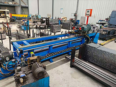
A typical production sequence can include tube cutting, end processing, shaft machining, bearing-related assembly, welding, and final inspection.
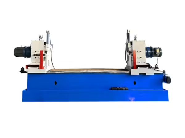
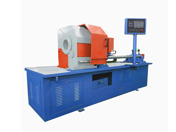
The conveyor roller processing machinery used for these operations illustrates why roller quality is created gradually through multiple manufacturing stages rather than in one final assembly step.
Tube cutting establishes initial geometry
Consistent tube length provides a predictable starting point for later operations.
If tube length varies significantly, assembly and final dimensions can become more difficult to control.
Shaft machining creates installation features
Shaft flats, grooves, slots, or other features need accurate positioning.
These dimensions affect whether finished rollers remain interchangeable within the conveyor structure.
Bearing assembly controls internal alignment
Bearings and housings need to remain positioned correctly relative to the shell and shaft.
Assembly fixtures and pressing methods can therefore influence rotational performance.
Welding should limit distortion
Where welding is part of the roller construction, heat input can influence finished geometry.
Fixtures need to hold the components in the correct relationship while the joint is produced.
The manufacturing goal is not simply to create a strong joint but to preserve the alignment created during earlier processes.
Metal Conveyor Rollers vs Non-Metal Roller Options
Metal is not the only material used for conveyor rollers.
Different materials can provide different characteristics, and the correct choice depends on the application.
| Evaluation Factor | Metal Conveyor Rollers | Non-Metal Roller Options |
|---|---|---|
| Structural rigidity | Generally high | Depends strongly on material |
| Load capability | Suitable for many industrial loads | Application dependent |
| Component mass | Usually higher | Can be lower |
| Corrosion behavior | May require suitable protection | Depends on material chemistry |
| Temperature capability | Depends on metal and bearings | Material dependent |
| Impact resistance | Depends on construction | Varies by material |
| Noise behavior | Depends on system | Some materials may reduce contact noise |
| Surface interaction | Metal contact | Can provide different contact behavior |
The table should not be interpreted as one material being universally superior.
The correct material is the one that satisfies mechanical, environmental, and operational requirements simultaneously.
How to Specify Metal Conveyor Rollers More Accurately
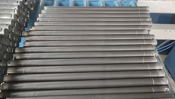
A complete technical specification should describe the actual operating condition.
Providing only roller diameter and length leaves many important variables undefined.
A stronger specification includes information about:
- Conveyor type
- Roller position
- Belt or product width
- Normal load
- Roller diameter
- Roller length
- Shaft dimensions
- Shaft-end geometry
- Bearing requirements
- Roller spacing
- Conveyor speed
- Operating environment
- Surface requirements
- Duty cycle
Technical drawings are especially valuable where shaft ends or mounting structures are more complex.
Define normal conditions first
It can be tempting to specify every component around an extreme operating condition.
A more practical approach is to identify normal production conditions first and then define reasonable margins for occasional variation.
This helps avoid unnecessary complexity while still providing suitable operating capacity.
Separate functional dimensions from secondary dimensions
Some dimensions directly affect installation, rotation, or load transfer.
Others are less critical.
Defining which characteristics are function-critical helps manufacturers focus process control and inspection on the dimensions that matter most.
Why Repeated Roller Failure Should Trigger System Inspection
When the same metal conveyor rollers fail repeatedly at one location, replacing the component may not address the original cause.
The surrounding conveyor should also be investigated.
Check alignment
Incorrect mounting geometry can increase bearing or shell loading.
Check the frame
Bent or damaged brackets can change the position of the roller relative to neighboring components.
Check material buildup
Accumulated material may interfere with roller rotation or belt contact.
Check the operating load
Actual loading may differ from the conditions assumed when the roller was originally specified.
Check neighboring components
A seized roller, damaged belt, or misaligned idler set can change the forces acting on adjacent rollers.
Repeated failure is therefore useful diagnostic information.
It may reveal a system-level problem rather than simply an inadequate roller.
What Should Be Inspected on Finished Metal Conveyor Rollers?
Quality inspection should focus on features related to actual operation.
| Inspection Item | Functional Importance |
| Roller diameter | Confirms system geometry |
| Roller length | Supports installation compatibility |
| Shaft dimensions | Ensures correct mounting |
| Shaft-end features | Supports interchangeability |
| Bearing position | Influences internal alignment |
| Runout | Indicates rotational geometry |
| Rotation | Helps identify abnormal resistance |
| Seal assembly | Protects internal components |
| Weld condition | Supports structural consistency |
| Surface condition | Reflects manufacturing and handling quality |
For repeated production, several rollers should be checked to understand process consistency.
A single acceptable component proves individual capability. Consistent results across a batch provide stronger evidence that the manufacturing process itself is stable.
A Better Way to Evaluate Metal Conveyor Rollers
The most useful roller evaluation combines component specifications with the conveyor environment.
Instead of asking only whether the roller is strong enough, consider whether it is mechanically balanced.
Does the shell suit the load and roller length?
Does the shaft suit the bearing spacing?
Do the bearings suit the load and speed?
Does the sealing arrangement suit the environment?
Does the mounting geometry match the frame?
Is the roller spacing appropriate for the material being transported?
Can the manufacturing process reproduce the same geometry consistently?
When these questions are answered together, roller selection becomes much more reliable.
Conclusion
Metal conveyor rollers are structural and rotational components that operate continuously as part of a larger conveyor system.
Their performance cannot be determined by material or diameter alone.
Shell thickness and diameter influence structural behavior. Shaft geometry transfers the load into the frame. Bearings determine rotational performance. Seals protect the internal assembly. Surface condition affects environmental suitability and product or belt interaction.
Manufacturing accuracy adds another layer.
Tube preparation, shaft machining, bearing positioning, welding, and assembly all influence finished roller geometry. Runout and rotational resistance therefore reflect the quality of the complete manufacturing process rather than one isolated component.
The surrounding conveyor also matters.
Roller spacing, frame alignment, loading conditions, belt behavior, and installation accuracy can determine whether a well-designed roller performs as expected.
For this reason, the most effective specification process starts with the application.
Define the load, conveyor geometry, roller position, environment, mounting arrangement, and operating duty first. Then select shell, shaft, bearing, sealing, and surface characteristics around those requirements.
A reliable metal conveyor roller is not simply a strong metal cylinder.
It is a balanced mechanical assembly designed to carry the intended load, rotate consistently, fit the conveyor accurately, and maintain predictable performance across repeated operation.
FAQ
What are metal conveyor rollers used for?
Metal conveyor rollers support belts or transported products in industrial conveying systems. Depending on their position, they may carry loads, support the return belt, absorb loading-zone forces, or form part of a roller conveyor. Their construction should match load, speed, spacing, environment, and mounting geometry.
How do I choose the correct metal conveyor rollers?
Begin with conveyor type, roller position, load, belt or product width, spacing, speed, and operating environment. Then select suitable roller diameter, shell thickness, shaft geometry, bearings, seals, surface condition, and mounting dimensions based on the complete mechanical requirement.
Why does wall thickness matter in metal conveyor rollers?
Wall thickness contributes to the structural behavior of the roller shell under load. It should be considered together with diameter, roller length, shaft design, bearing position, and load distribution. Increasing wall thickness alone cannot compensate for an unsuitable shaft or poorly aligned bearing system.
What causes metal conveyor rollers to develop excessive runout?
Excessive runout can result from tube geometry, bearing-seat misalignment, inaccurate shaft machining, assembly variation, or welding distortion. Consistent manufacturing and inspection are important because runout affects how the roller surface interacts with the conveyor belt or transported product.
How can metal conveyor roller service life be improved?
Suitable roller specification, correct installation, reliable sealing, proper alignment, controlled loading, and routine inspection all contribute to longer service. Repeated problems should also prompt inspection of the conveyor frame, neighboring rollers, contamination, and actual operating conditions.
 English
 French
 Spanish