

Table of Contents
Introduction
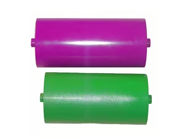
Industrial conveyor rollers are designed to support continuous material movement under operating conditions that are often far more demanding than occasional or light-duty conveying. In a working conveyor, rollers repeatedly carry belt tension, transported material, dynamic loading, vibration, contamination, and rotational forces. Their reliability therefore depends on the complete mechanical design rather than on roller diameter or shell material alone.
A well-designed industrial roller needs sufficient structural stability to support the intended load while maintaining consistent rotation over long operating periods. The shell, shaft, bearings, seals, mounting structure, and manufacturing accuracy all contribute to this performance. If one part of the assembly is poorly matched to the application, the entire roller can become less reliable even when the remaining components are correctly designed.
The surrounding conveyor is equally important. Roller spacing determines how loads are distributed, while frame alignment affects shaft and bearing relationships. Belt tracking, loading position, operating speed, and environmental conditions can also change the forces experienced by individual rollers. This is why industrial conveyor rollers should be selected according to the complete operating environment rather than treated as interchangeable cylindrical parts.
Understanding these relationships makes it easier to choose suitable rollers, diagnose recurring problems, and evaluate manufacturing quality. The following sections explain the main engineering factors that influence industrial conveyor roller performance and how those factors work together during continuous operation.
How Industrial Conveyor Rollers Support a Conveyor System
In a typical conveyor system, rollers provide repeated support along the material-handling route. Depending on the conveyor design, they may support a loaded belt, guide a returning belt, absorb forces near a loading zone, or directly carry unit loads.
The forces acting on a roller are transferred through several components. The shell receives contact from the belt or product, the bearings transfer that force toward the shaft, and the shaft passes it into the mounting brackets or conveyor frame. This mechanical relationship means roller performance should always be evaluated as a load path rather than as the strength of one individual part.
A thicker shell, for example, may improve local structural capability, but it cannot correct excessive shaft deflection or poor bearing alignment. Likewise, larger bearings will not solve a problem caused by incorrect frame geometry. Reliable industrial conveyor rollers are created when the shell, shaft, bearings, sealing arrangement, and supporting structure are designed to work under the same operating conditions.
This becomes particularly important in long conveyor systems because the effect of one poorly performing roller can extend beyond its immediate position. Increased rotational resistance, misalignment, or abnormal runout can influence belt behavior and place additional demands on neighboring components.
Roller Diameter, Shell Thickness, and Length Need to Be Balanced
Roller diameter is one of the first specifications considered during selection, but diameter alone does not determine whether a roller is suitable for industrial use. The relationship between diameter, shell thickness, working length, bearing position, and applied load is more important.
A longer roller experiences a different bending condition from a shorter roller with the same construction. As working length increases, shell and shaft stiffness become increasingly important because the component must maintain its intended geometry between the support points.
Shell thickness also contributes to structural stability. A shell that is too light for the operating load may deflect more than intended, while increasing thickness unnecessarily can add rotating mass without improving the parts of the roller that actually limit performance.
The most effective design therefore balances all major dimensions. Diameter should suit the conveyor geometry and load. Wall thickness should support the shell across its working length. Bearing positions should provide suitable support, and the shaft should transfer the resulting forces into the conveyor structure without excessive deformation.
A practical roller specification should consider these dimensions together.
| Design Factor | Why It Matters |
|---|---|
| Roller diameter | Influences geometry, stiffness and available internal space |
| Shell thickness | Supports the roller body under load |
| Roller length | Changes bending conditions and support requirements |
| Bearing position | Influences load transfer through the roller |
| Shaft diameter | Supports the assembly and transfers load to the frame |
| Mounting geometry | Determines installation compatibility and alignment |
This relationship is one reason industrial roller design should begin with the application rather than by copying one catalogue dimension from an existing component.
Shaft Design Determines How Loads Reach the Conveyor Frame
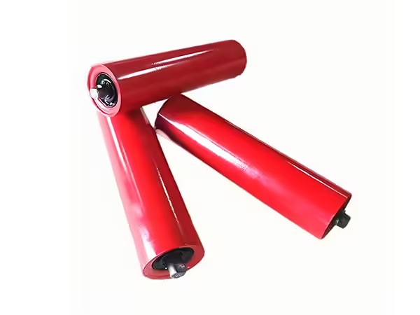
The shaft is one of the most important structural parts of industrial conveyor rollers because it connects the rotating assembly to the stationary conveyor structure. Although much of the shaft may be hidden inside the roller, its dimensions and mounting features influence both load capacity and installation accuracy.
A conveyor roller shaft can include flats, grooves, slots, threaded sections, stepped diameters, or other features required by the conveyor frame. These features need to be positioned consistently because they determine how the finished roller fits into the supporting structure.
Shaft stiffness also matters. If the shaft bends excessively under operating load, the relationship between the bearings and roller shell may change. This can create uneven bearing loading, increased rotational resistance, or abnormal roller geometry.
For industrial applications, shaft design should therefore consider roller length, bearing spacing, load distribution, mounting method, and operating duty together. The shaft should not simply be selected according to diameter without understanding how it is supported.
Replacement projects require particular attention to shaft-end geometry. Two industrial conveyor rollers may have the same shell diameter and face length but still be incompatible because their shaft ends connect to the conveyor differently. Technical drawings can prevent this type of mismatch by defining the dimensions that actually control installation.
Bearings and Seals Have a Major Influence on Roller Reliability
Bearings allow the roller shell to rotate while carrying load, making them one of the most important functional components inside an industrial roller. Their performance depends on more than nominal bearing size. Load, speed, shaft alignment, assembly accuracy, contamination, and operating duration all influence how the bearing behaves over time.
A bearing that works satisfactorily in a relatively clean conveyor may not provide the same result in a system exposed to dust or material residue. Likewise, a bearing arrangement suitable for one roller length may behave differently when installed in a longer roller with greater shaft deflection.
Sealing systems are therefore closely connected with bearing performance. Their purpose is to reduce the amount of contamination reaching the internal bearing area while allowing the roller to rotate with suitable resistance.
The correct sealing arrangement depends on the operating environment. Dust, fine particles, moisture, material carryback, and cleaning procedures can all change the level of protection required. A highly contaminated application may need a more protective sealing structure than a conveyor operating in a controlled environment.
At the same time, sealing should not introduce unnecessary rotational resistance. The most effective arrangement balances protection with smooth operation, making bearing, seal, shaft, and assembly design part of one internal system.
The construction of conveyor rollers can therefore vary according to application, dimensions, bearing arrangements, shaft requirements, and environmental conditions rather than following one standard internal design for every conveyor.
Roller Spacing Changes Load Distribution and Belt Support
Industrial conveyor rollers work as a group, which means the spacing between them has a direct influence on how the conveyor behaves. A roller that performs correctly at one spacing may experience a different load when the distance between supporting positions changes.
In a belt conveyor, the belt transfers material load across consecutive idler positions. If the spacing becomes wider, fewer supporting points carry the same section of belt and material. This can change belt sag and increase the forces acting on individual rollers.
In a roller conveyor, spacing determines how many rollers remain beneath the transported product. A short product moving across widely spaced rollers may receive less support than a longer product moving over the same conveyor.
For this reason, roller capacity and roller spacing should be considered together. Increasing roller strength without reviewing the supporting geometry may not solve a conveyor problem caused by unsuitable spacing.
Spacing also affects the total number of rollers operating in the system. More rollers can provide more frequent support, but they also introduce additional bearings, shafts, and rotating components that need to remain aligned and maintained. The best arrangement is therefore the one that provides sufficient support for the application without unnecessary complexity.
Different Conveyor Positions Create Different Roller Requirements
Industrial conveyor rollers are not always interchangeable because their operating conditions change along the conveyor route. Carrying rollers, return rollers, and impact rollers each perform a different function and may experience different loads or environmental exposure.
Carrying rollers operate beneath the loaded section of a belt conveyor. They support both the belt and the transported material, so their design needs to reflect belt width, material load, spacing, operating speed, and idler geometry.
Return rollers support the belt after material has been discharged. The direct load is normally different, but these rollers may encounter contamination carried back on the belt surface. Material buildup can influence both surface contact and rotational behavior if it is not considered during roller selection.
Impact positions create another operating condition. Material entering the conveyor can generate dynamic loading that differs from the relatively steady forces found along normal carrying sections. These areas may require roller or idler arrangements designed specifically to manage the loading environment.
The same principle applies to transition zones and other specialized conveyor positions. Industrial conveyor rollers should therefore be specified according to where they operate rather than assuming one construction is appropriate throughout the complete conveyor.
Manufacturing Accuracy Has a Direct Effect on Continuous Operation
Industrial roller performance begins during manufacturing. A roller can be correctly specified on paper but still operate poorly if tube preparation, shaft machining, bearing positioning, or final assembly introduce excessive variation.
Tube cutting establishes the basic roller body length. Shaft machining creates mounting and locating features. Bearing-related operations determine the internal alignment of the rotating assembly, while welding can introduce heat and distortion where it forms part of the construction.
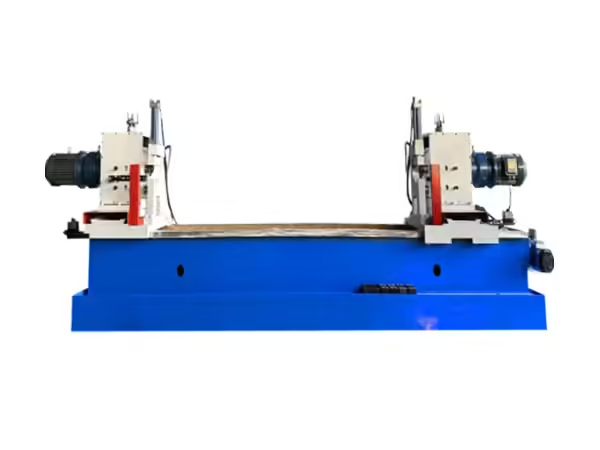
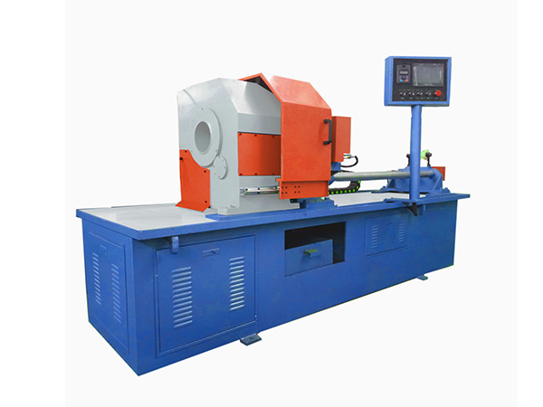
Specialized conveyor roller processing machinery addresses these recurring production stages because finished roller quality is created progressively rather than only during final inspection.
Manufacturing consistency becomes particularly important for industrial systems that contain many rollers. If each roller varies slightly in length, runout, shaft position, or rotational resistance, the cumulative difference across a long conveyor can become more significant than it appears when the components are inspected individually.
Repeatability is therefore one of the most useful measures of production quality. One acceptable roller demonstrates that the product can be manufactured, while consistent results across repeated units demonstrate that the manufacturing process is under control.
This is especially important for replacement components. A stable production process improves interchangeability and reduces the need for modification during installation.
Runout and Rotational Resistance Can Reveal Manufacturing Problems
Runout describes the variation in the outer roller surface relative to its rotational axis. Excessive runout can cause repeated movement at the belt or product contact surface and may contribute to vibration, uneven support, or unstable material movement.
Runout can originate from several manufacturing stages. Tube roundness, shell straightness, bearing-seat positioning, shaft alignment, welding distortion, and assembly accuracy can all influence final rotational geometry.
Because of this, runout should not be treated only as a final inspection result. It is also an indication of how well the earlier production processes have been controlled.
Rotational resistance provides another useful indicator. A roller that requires noticeably more force to rotate than similar rollers may have issues related to bearing condition, seal installation, contamination, shaft alignment, or internal assembly.
Industrial conveyor rollers should therefore be evaluated both dimensionally and functionally. Correct diameter and length do not automatically guarantee acceptable rotation.
When several rollers are tested from one production batch, differences between them can also reveal process variation that would be impossible to identify by inspecting only one sample.
Surface Condition and Material Should Match the Operating Environment
Metal rollers are common in industrial conveyors because they can provide strong structural support and stable geometry, but surface conditions still need to match the application.
A roller exposed to moisture or corrosive conditions may require a different material or surface treatment from one operating in a relatively controlled environment. Likewise, a roller that contacts conveyed products directly may have different surface requirements from an idler supporting the underside of a belt.
Surface protection should therefore have a defined purpose. It may be intended to improve environmental resistance, modify contact behavior, or protect the underlying material. Applying additional treatment without understanding the operating condition does not automatically improve roller performance.
Surface wear can also provide useful information during maintenance. Uneven wear across a roller may indicate abnormal loading, misalignment, material buildup, or inconsistent belt contact. If the same wear pattern appears repeatedly in one conveyor position, the surrounding system should be examined before the roller is simply replaced again.
Alignment Is a System Requirement, Not Just a Roller Requirement
An accurately manufactured industrial conveyor roller can still operate poorly when installed in an incorrectly aligned frame. The supporting structure determines roller position, shaft alignment, spacing, and the relationship between neighboring components.
If mounting brackets are not positioned correctly, the roller may be forced into an unintended angle. This can change bearing loading or influence the way the belt contacts the roller surface.
Misalignment can also create symptoms away from the actual source of the problem. A roller installed incorrectly near the beginning of a conveyor section may influence belt behavior further downstream, causing operators to adjust other components that are not responsible for the original deviation.
For this reason, repeated roller or bearing problems at the same position should prompt inspection of the frame, mounting brackets, adjacent idlers, belt condition, and material loading.
The roller should be considered part of the conveyor geometry rather than an independent rotating component.
What Should Be Checked When Selecting Industrial Conveyor Rollers?
A useful industrial roller specification describes the actual operating environment rather than providing only basic dimensions. Roller diameter and length remain important, but they should be supported by information about load, speed, shaft geometry, mounting structure, environmental exposure, and conveyor position.
A practical specification can include the following:
| Specification Area | Information to Confirm |
| Conveyor type | Belt conveyor, roller conveyor or specialized system |
| Roller position | Carrying, return, impact or other location |
| Load | Normal operating load and loading behavior |
| Roller dimensions | Diameter, length and shell construction |
| Shaft | Diameter, end geometry and mounting method |
| Bearings | Load, speed and assembly requirements |
| Sealing | Dust, moisture and contamination exposure |
| Roller spacing | Relationship with belt or transported product |
| Environment | Temperature, moisture, dust and material residue |
| Operating duty | Speed, duration and start-stop conditions |
| Quality control | Runout, dimensions and rotational inspection |
This information provides a much stronger basis for roller design than simply requesting an “industrial” or “heavy-duty” component.
Industrial duty should describe the actual mechanical conditions rather than function as a general marketing term.
Why Repeated Roller Failures Need Root-Cause Analysis
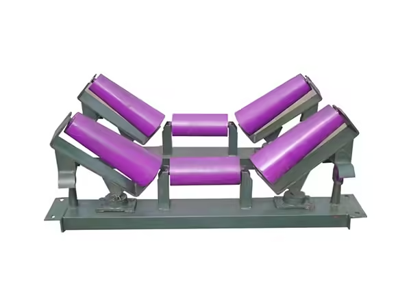
When industrial conveyor rollers repeatedly fail in the same area, replacing them without examining the conveyor can result in the same problem returning.
Bearing failures may be related to contamination, frame misalignment, excessive shaft loading, or incorrect installation. Abnormal shell wear may indicate material buildup or unusual belt contact. Repeated runout problems can sometimes result from operating loads or installation conditions rather than manufacturing alone.
Maintenance teams can gain useful information by comparing the same roller type across several conveyor positions. If most rollers operate normally but components in one area repeatedly require attention, the local conveyor condition deserves investigation.
The inspection should consider the frame, mounting brackets, neighboring rollers, material loading, belt behavior, contamination, and actual operating duty. Changes in production conditions should also be reviewed because the conveyor may now be carrying loads different from those assumed when the rollers were originally specified.
A failed roller is therefore not only a replacement requirement. It is also evidence that can help diagnose the mechanical behavior of the conveyor.
Conclusion
Industrial conveyor rollers need to perform reliably as part of a continuous mechanical system, which means their design cannot be reduced to shell material, diameter, or nominal load capacity. The shell, shaft, bearings, seals, mounting geometry, and surface condition all contribute to the way forces are transferred through the roller and into the conveyor structure. These relationships become increasingly important as operating loads, conveyor length, duty cycles, and environmental exposure increase.
Manufacturing accuracy is equally important because dimensional variation introduced during tube preparation, shaft machining, bearing installation, welding, or assembly can affect runout and rotational consistency after installation. In an industrial conveyor containing many rollers, small differences between individual components can accumulate into noticeable changes in belt support, vibration, or resistance. Stable production therefore depends on repeatable manufacturing rather than the quality of one isolated sample.
The surrounding conveyor must also be considered during roller selection. Spacing, frame alignment, belt behavior, loading position, operating speed, and contamination can all change the demands placed on an individual roller. When repeated failures occur in the same location, these system conditions should be investigated before assuming that the roller itself is the only cause.
Selecting industrial conveyor rollers should therefore begin with a clear understanding of the actual application. Once the load, conveyor geometry, roller position, mounting method, speed, environmental exposure, and operating duty are defined, the shell, shaft, bearings, seals, and other construction details can be matched more accurately. This system-based approach provides a stronger foundation for stable material handling and more predictable long-term conveyor operation.
FAQ
What are industrial conveyor rollers used for?
Industrial conveyor rollers support belts, transported materials, or unit loads during continuous conveying. Depending on their position, they may operate as carrying, return, impact, or direct-support rollers. Their construction should match load, speed, spacing, mounting geometry, environment, and duty cycle.
How are industrial conveyor rollers different from standard rollers?
Industrial conveyor rollers are normally specified around demanding operating conditions such as continuous duty, higher loads, contamination, longer conveyor routes, or specific mounting requirements. The difference should come from the actual engineering specification rather than simply from an “industrial” product label.
What determines the load capacity of industrial conveyor rollers?
Load capability depends on the combined design of the roller shell, diameter, wall thickness, shaft, bearing positions, mounting spacing, material, and roller length. Conveyor spacing also matters because it determines how the total load is distributed between adjacent supporting rollers.
Why do bearings fail in industrial conveyor rollers?
Bearing problems can result from contamination, misalignment, incorrect assembly, unsuitable loading, shaft deflection, seal problems, or installation errors. Repeated failures at the same conveyor position should prompt inspection of the surrounding frame, load distribution, and operating environment.
How should industrial conveyor rollers be inspected?
Inspection can include roller dimensions, shaft-end geometry, bearing position, runout, rotational resistance, sealing condition, surface condition, and overall assembly. For repeated production, several rollers should be checked so that manufacturing consistency can be evaluated rather than relying on one sample
 English
 French
 Spanish