
Table of Contents
Introduction
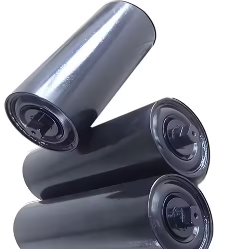
Rollers are among the most frequently repeated components in a conveyor system, yet their influence is much larger than their size suggests. Every roller contributes to belt support, load distribution, tracking behavior, rotational resistance, vibration, and the way forces are transferred into the conveyor structure.
For that reason, selecting rollers for conveyor systems should never be reduced to matching diameter and length.
A roller may fit perfectly into an existing bracket and still perform poorly if its shaft construction, bearing arrangement, sealing system, shell thickness, runout, or application type does not match the operating conditions. Problems can become more obvious when hundreds of rollers are working together because small inconsistencies are repeated throughout the system.
A stronger selection method starts with the operating position and works outward toward the component specification.
Key considerations include:
- Determine whether the roller is carrying, returning, impacting, or guiding the belt.
- Evaluate actual load distribution rather than only maximum load.
- Match roller diameter, shell thickness, shaft, and bearings as one assembly.
- Consider sealing according to dust, moisture, and contamination exposure.
- Control runout and rotational resistance for stable belt movement.
- Match idler geometry with belt width and conveying requirements.
- Treat installation alignment as part of roller performance.
- Evaluate manufacturing consistency when large quantities are required.
- Design maintenance around the conveyor’s actual operating conditions.
Understanding these relationships helps you select rollers that support the complete conveyor rather than simply replace an individual component.
Why Rollers for Conveyor Matter More Than They Appear
A conveyor system combines moving and supporting components to transport materials between locations. In belt conveying systems, rollers form the mechanical support beneath the belt and help maintain its intended path throughout both the carrying and return sections.
A single roller normally represents only a small part of the conveyor.
Collectively, however, rollers can influence:
- Belt profile
- Material stability
- Running resistance
- Tracking
- Vibration
- Noise
- Component wear
- Maintenance frequency
This creates an important engineering principle:
The conveyor does not experience one roller. It experiences the combined behavior of every roller along its route.
Small differences become system-level differences
Suppose one roller has slightly higher rotational resistance than another.
On its own, the difference may seem minor.
When many rollers develop inconsistent resistance, however, the belt system can experience greater cumulative drag. Likewise, inconsistent mounting positions or excessive roller runout can create repeated disturbances along the conveyor.
This is why rollers for conveyor applications should be evaluated for consistency as well as individual strength.
Start With the Function of the Conveyor Roller
The operating position should be identified before dimensions are finalized.
Different rollers perform different jobs.
The conveyor rollers used in belt systems can include carrying, troughing, return, impact, training, self-aligning, garland, and other configurations according to their position and operating purpose.
Carrying Rollers
Carrying rollers support the loaded side of the conveyor belt.
They need to support the combined belt and material load while maintaining the required belt profile.
Selection should consider:
- Belt width
- Material load
- Roller spacing
- Conveyor speed
- Trough arrangement
- Shaft construction
- Bearing capacity
- Installation geometry
In many bulk material conveyors, carrying rollers are arranged into troughing sets rather than installed completely flat.
Return Rollers
Once material has been discharged, the belt returns toward the loading area.
Return rollers support this unloaded belt path.
Although the bulk material is no longer present, return-side conditions can include:
- Material sticking to the belt
- Dust
- Moisture
- Misalignment
- Belt movement
- Long operating periods
Return rollers should therefore still be selected according to their environment and duty.
Impact Rollers
Loading zones create a different mechanical condition.
Material entering the conveyor may fall onto the belt, creating dynamic forces. Impact roller arrangements are intended to help support the belt while managing these localized loading conditions.
A standard carrying roller should not automatically be assumed suitable for every loading zone.
Training and Self-Aligning Rollers
Tracking problems can cause the belt to move toward one side of the conveyor.
Training and self-aligning roller arrangements can assist belt guidance, although they should be used together with correct structural alignment and loading conditions.
Persistent tracking problems should also trigger inspection of:
- Conveyor frame alignment
- Pulley alignment
- Material loading position
- Roller installation
- Belt condition
- Material buildup
A training roller is part of a tracking strategy, not a substitute for correcting a fundamentally misaligned conveyor.
Roller Diameter Is Only One Part of the Specification
Diameter is usually one of the first specifications buyers compare.
It matters, but it should not be evaluated independently.
A practical roller design combines:
Roller diameter + shell thickness + roller length + shaft + bearings + seals + operating conditions.
How diameter affects the roller
The selected diameter may influence:
- Structural behavior
- Rotational characteristics
- Available bearing arrangement
- Shaft configuration
- Installation dimensions
- Belt interaction
Larger is not automatically better.
The most appropriate size depends on the application’s operating requirements.
Shell thickness matters under load
The roller shell transfers belt and material forces toward the internal bearing and shaft structure.
If shell construction is unsuitable, deformation can affect the relationship between the roller surface and the belt.
However, simply increasing shell thickness does not guarantee a reliable roller.
If the shaft, bearing, housing, or assembly method becomes the limiting factor, a heavier shell alone provides limited benefit.
Length must match conveyor geometry
Roller length is closely related to belt width and idler configuration.
For troughing sets, several rollers collectively support the belt. Their individual lengths and installation angles create the final belt profile.
The correct dimension therefore comes from the entire conveyor geometry rather than from roller size alone.
Load Distribution Should Guide Roller Selection
When selecting rollers for conveyor applications, a maximum load value does not fully describe the working condition.
You also need to know how the load reaches each roller.
Continuous loads
Along a normal carrying section, material load is distributed through the belt into successive idler sets.
Roller spacing affects how much load each support location receives.
Increasing the distance between supports can change belt sag and the forces experienced by individual idlers.
Impact loads
The loading zone behaves differently.
Material may enter with vertical velocity, producing impact forces beyond the normal static load.
This is why impact positions often require a different roller arrangement from standard carrying sections.
Uneven loading
Materials do not always remain perfectly centered.
Uneven loading may create different forces across the trough.
If material consistently accumulates toward one side, the problem may also contribute to belt-tracking behavior.
A useful load checklist
Before selecting the roller, determine:
| Load Factor | Question to Ask |
|---|---|
| Material type | What material is being transported? |
| Normal load | What does the conveyor carry during typical operation? |
| Peak condition | Are temporary load increases expected? |
| Impact | Does material fall onto this conveyor section? |
| Distribution | Is material centered across the belt? |
| Idler spacing | How far apart are roller sets installed? |
| Belt geometry | Is the belt flat or troughed? |
| Duty cycle | How continuously does the conveyor operate? |
These questions provide more useful engineering information than a single capacity number.
Bearings and Seals Are Critical Inside Rollers for Conveyor
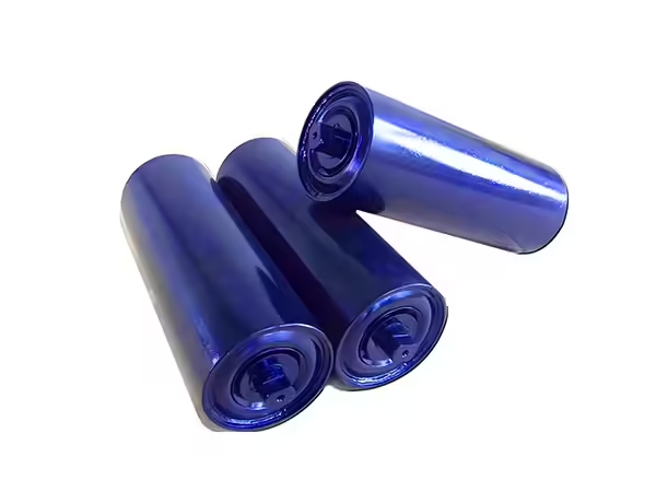
The shell is the most visible part of a roller, but many long-term performance issues originate inside it.
Bearings allow the shell to rotate around the shaft, while sealing systems help protect the internal assembly from environmental contamination.
Both deserve careful consideration.
Bearing requirements
Bearing selection can depend on:
- Radial load
- Roller diameter
- Shaft dimensions
- Rotational speed
- Operating duration
- Installation accuracy
- Environmental conditions
- Internal assembly geometry
A bearing should be considered as part of the complete roller rather than selected according to size alone.
Bearing alignment
Both bearing positions need to maintain the intended relationship with the roller shell and shaft.
Misalignment can contribute to:
- Higher rotational resistance
- Uneven bearing loading
- Vibration
- Premature wear
- Unstable rotation
This places considerable importance on bearing-housing manufacturing and assembly consistency.
Sealing against contamination
Conveyors often operate where dust, particles, moisture, or material residue are present.
A suitable sealing arrangement helps isolate the bearing environment.
When evaluating seals, consider:
- Type of contamination
- Exposure level
- Roller position
- Shaft interface
- Moisture
- Operating speed
- Maintenance accessibility
A highly protected internal arrangement should still allow the roller to rotate appropriately for its application.
The goal is balance, not simply maximum sealing contact.
Runout and Rotational Resistance Affect Belt Stability
Two rollers can have identical nominal dimensions and still behave differently during operation.
Runout and rotational resistance help explain why.
What roller runout tells you
Runout describes the variation in the roller surface as it rotates around its axis.
Potential sources include:
- Tube geometry
- Bearing-seat positioning
- Shaft geometry
- Welding distortion
- Assembly variation
Excessive runout can create repeated movement at the belt contact surface.
Across many rollers, this may contribute to vibration or less stable belt support.
What rotational resistance tells you
Rotational resistance describes how much resistance the roller presents while turning.
It can be affected by:
- Bearings
- Seals
- Internal alignment
- Contamination
- Assembly fit
- Shaft geometry
There is no value in pursuing extremely low resistance if doing so compromises sealing or operating reliability.
A suitable roller needs balanced rotational behavior for the environment in which it will operate.
Consistency matters across a conveyor
One unusually resistant roller may be noticed during inspection.
A larger concern is when variation becomes widespread throughout the conveyor.
For projects using substantial quantities of rollers, production consistency therefore deserves almost as much attention as individual specifications.
Roller Sets Must Work as One Geometric System
In many belt conveyors, rollers are installed in groups.
The individual rollers, mounting brackets, angles, and belt jointly form a support system.
A conveyor roller set should therefore be evaluated as a complete assembly rather than as several unrelated rollers.
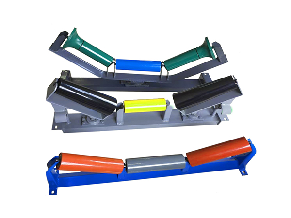
Troughing Sets
A troughing arrangement commonly combines a center roller with angled wing rollers.
Together they shape and support the loaded belt.
Performance depends on:
- Roller angles
- Belt width
- Roller lengths
- Bracket geometry
- Material distribution
- Installation accuracy
Changing the geometry of one component may change the way the entire set supports the belt.
Flat Sets
Flat roller arrangements support the belt without creating a trough.
They may be appropriate in specific conveyor sections according to belt design and material-handling requirements.
Impact Sets
Loading areas may require impact-oriented roller sets to manage dynamic forces.
The roller itself is only part of the solution.
Supporting brackets, installation geometry, material drop conditions, and belt behavior also influence how effectively the loading zone performs.
Self-Aligning Sets
Self-aligning arrangements are intended to respond to belt tracking behavior.
Their performance still depends on correct installation and suitable surrounding conveyor geometry.
Materials Should Match the Operating Environment
Choosing materials for rollers for conveyor systems involves more than determining mechanical strength.
The operating environment also matters.
Steel rollers
Steel roller construction is commonly used where strength and industrial durability are required.
Performance also depends on:
- Wall thickness
- Surface protection
- Welding quality
- Shaft design
- Bearing assembly
- Environmental exposure
The material specification should therefore include the complete roller structure.
Polymer-based rollers
Polymer-based rollers may be considered for applications where particular material characteristics are beneficial.
Potential considerations include:
- Component mass
- Corrosion behavior
- Noise
- Surface interaction
- Wear
- Environmental exposure
Suitability still depends on load, speed, temperature, impact, and dimensional requirements.
Rubber-covered or impact rollers
Resilient surface elements can be useful where shock absorption or specific belt interaction is needed.
Their role should be defined by the operating position rather than applied throughout the conveyor without technical justification.
How Manufacturing Quality Changes Roller Performance
Rollers for conveyor systems are often needed in relatively large quantities.
This makes manufacturing repeatability particularly important.
A good roller production process needs to control several interconnected operations.
Tube cutting
Consistent tube length creates a predictable starting point for subsequent operations.
Variation at this stage can influence later assembly geometry.
Tube-end and bearing-seat preparation
Bearing housings and related components need reliable positioning relative to the roller shell.
Their alignment influences internal assembly accuracy.
Shaft machining
The shaft may contain flats, grooves, slots, threads, or stepped geometries depending on the mounting method.
These features need repeatable positioning if rollers are expected to be interchangeable.
Assembly
Bearings, seals, shafts, housings, and shell components must come together in a controlled sequence.
An individually accurate component can still produce an inconsistent roller if assembly position varies.
Welding
Where welding is used, fixtures should maintain component geometry while the joint is produced.
Excessive distortion can influence finished roller alignment or runout.
Final inspection
A practical roller inspection plan can include:
| Inspection Item | Purpose |
|---|---|
| Roller diameter | Confirms dimensional requirement |
| Roller length | Confirms installation compatibility |
| Shaft dimensions | Confirms mounting fit |
| Shaft-end geometry | Supports interchangeability |
| Runout | Checks rotational geometry |
| Rotation | Evaluates assembly behavior |
| Bearing position | Supports internal alignment |
| Seal installation | Confirms internal protection |
| Weld condition | Checks assembly integrity |
| Surface condition | Identifies manufacturing or handling issues |
Inspection should focus on characteristics that matter to real conveyor operation.
How to Select Rollers for Conveyor Applications
A useful selection process can be completed in stages.
Step 1: Identify conveyor type
Determine whether the roller supports:
- A conveyor belt
- Unit loads directly
- A return belt
- A loading zone
- A special guiding function
This prevents the wrong roller family from being considered.
Step 2: Identify installation position
Specify whether the roller will be used as:
- Carrying roller
- Trough roller
- Return roller
- Impact roller
- Training roller
- Self-aligning roller
- Other special arrangement
Step 3: Define conveyor dimensions
Prepare:
- Belt width
- Roller diameter
- Roller length
- Shaft dimensions
- Mounting distance
- Idler angle
- Roller-set configuration
Step 4: Define material and loading conditions
Provide information about:
- Material handled
- Normal load
- Loading method
- Impact conditions
- Material distribution
Step 5: Describe the environment
Include:
- Dust
- Moisture
- Contamination
- Temperature conditions
- Outdoor exposure
- Material buildup
This information helps determine appropriate sealing, material, and internal construction.
Step 6: Define operating characteristics
Consider:
- Conveyor speed
- Operating duration
- Starts and stops
- Continuous or intermittent operation
- Maintenance intervals
Step 7: Review drawings
Technical drawings are especially useful for replacement rollers.
They can communicate:
- Overall dimensions
- Shaft-end details
- Groove position
- Flat position
- Tube dimensions
- Bearing-related geometry
A drawing reduces the risk of relying on ambiguous dimensional descriptions.
Rollers for Conveyor: Common Selection Errors
Many conveyor problems start with seemingly small specification shortcuts.
Matching only diameter and length
External dimensions do not define the complete roller.
Shaft, bearings, seals, shell construction, mounting geometry, and roller function also need to match.
Assuming all conveyor positions use the same roller
Carrying, return, impact, and tracking zones operate differently.
Roller construction should reflect those differences.
Ignoring mounting dimensions
A roller can have the correct working length yet still be incompatible with the bracket if shaft-end geometry differs.
Ignoring alignment problems
Replacing rollers will not permanently correct belt problems caused by a distorted frame or incorrectly installed bracket.
Focusing only on shell strength
A stronger shell cannot compensate for unsuitable bearings, poor internal alignment, ineffective sealing, or incorrect shaft construction.
Evaluating only one sample
One good sample proves individual capability.
Larger orders require manufacturing repeatability.
Multiple samples provide better evidence of dimensional and rotational consistency.
What to Check When Conveyor Rollers Fail Repeatedly
Repeated roller problems should trigger investigation rather than automatic replacement.
If the same conveyor area experiences recurring failures, inspect the surrounding system.
Check belt tracking
A misaligned belt can apply unusual loads to idlers or surrounding structures.
Check material buildup
Accumulated material can interfere with roller rotation and belt contact.
Check idler brackets
Bent or incorrectly positioned brackets can change roller alignment.
Check loading conditions
Unexpected impact or off-center loading may create forces beyond the intended design condition.
Check neighboring rollers
One seized or damaged roller can alter the way the belt interacts with adjacent components.
Check roller specification
Verify that the installed roller actually matches:
- Application
- Load
- Speed
- Environment
- Mounting geometry
- Bearing requirements
- Sealing requirements
Repeated failure is useful diagnostic information. It should not automatically be treated as an isolated component event.
A Practical Specification Checklist
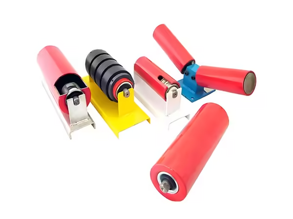
Before finalizing rollers for conveyor applications, prepare a specification covering the complete operating condition.
| Category | Information Required |
|---|---|
| Conveyor | Type and application |
| Roller position | Carrying, return, impact, training, etc. |
| Material | What the conveyor transports |
| Belt | Width and operating configuration |
| Roller | Diameter and length |
| Shaft | Diameter, length, end geometry |
| Set geometry | Flat or troughing configuration |
| Load | Normal and dynamic conditions |
| Speed | Conveyor operating speed |
| Environment | Dust, moisture, contamination |
| Bearings | Load and operating requirements |
| Seals | Environmental protection needs |
| Mounting | Bracket and installation geometry |
| Maintenance | Access and replacement expectations |
This type of specification gives the manufacturer enough information to understand the roller’s actual job.
It also makes technical comparisons more meaningful because competing configurations are being evaluated against the same requirements.
Conclusion
Selecting rollers for conveyor systems is not simply a matter of finding a cylinder with the correct dimensions.
A reliable roller needs to match its exact operating position.
Carrying rollers support the loaded belt. Return rollers support the returning belt. Impact rollers operate under dynamic loading. Training and self-aligning arrangements address particular belt-guidance requirements.
Once the function is established, the complete component needs to be considered.
Diameter, length, shell construction, shaft geometry, bearings, seals, runout, rotational resistance, material, and mounting arrangement all influence performance.
The surrounding conveyor matters just as much.
Correctly manufactured rollers can still perform poorly when brackets are misaligned, material loading is uneven, the belt tracks incorrectly, or idler-set geometry is unsuitable.
For large roller quantities, manufacturing repeatability adds another layer of importance. Consistent tube preparation, shaft machining, bearing positioning, assembly, welding, and inspection help make replacement components genuinely interchangeable.
So instead of asking:
“Which rollers fit this conveyor?”
A better engineering question is:
“Which rollers match the load, position, belt geometry, environment, mounting method, and operating conditions of this conveyor?”
That question leads to a more reliable specification and a stronger foundation for long-term conveyor performance.
FAQ
What types of rollers for conveyor systems are commonly used?
Common rollers include carrying, troughing, return, impact, training, and self-aligning types. Each performs a different function within the conveyor. Selection should be based on belt position, material load, conveyor geometry, operating environment, and required belt-support behavior.
How do I choose the right rollers for conveyor systems?
Start with roller function, belt width, load, idler spacing, conveyor speed, shaft dimensions, and mounting geometry. Then evaluate shell construction, bearings, seals, material, runout, and environmental conditions so the complete roller assembly matches actual operation.
Why do bearings matter when selecting rollers for conveyor systems?
Bearings support roller rotation under operating load. Their behavior depends on load, shaft geometry, speed, alignment, sealing, and assembly accuracy. Suitable bearings and correctly positioned housings help maintain stable rotation while reducing unnecessary resistance and uneven internal loading.
What causes conveyor rollers to wear prematurely?
Premature wear can result from contamination, damaged bearings, poor sealing, misalignment, excessive impact, material buildup, incorrect mounting, unsuitable roller specifications, or abnormal belt tracking. Repeated failures in one position often indicate a broader conveyor-system issue.
Can the same rollers for conveyor systems be used in every position?
Usually not. Carrying, return, impact, and training positions experience different loads and operating conditions. Although some dimensions may be similar, roller construction, surface configuration, sealing, mounting, and supporting geometry should reflect the specific function of each location.
 English
  French
  Spanish