

Table of Contents
Introduction
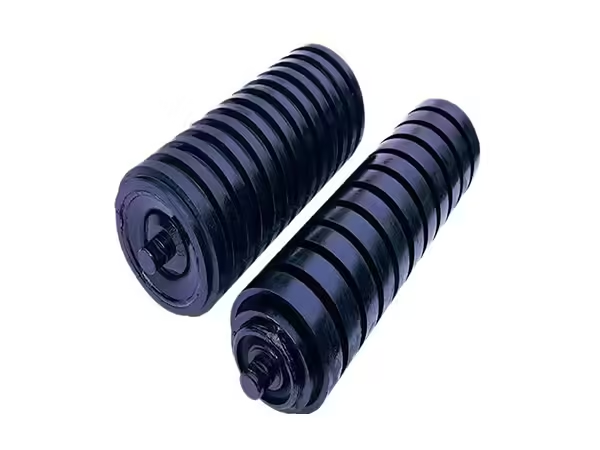
Conveyor rollers and idlers are closely related terms in belt conveyor engineering, which is why they are often used interchangeably. However, they do not always describe exactly the same thing. A conveyor roller is normally the individual cylindrical rotating component that contacts and supports the belt, while an idler usually refers to the non-powered support function or, in many industrial contexts, the complete roller-and-frame arrangement installed beneath the belt.
Understanding this distinction becomes important when specifying equipment for mining, quarrying, cement, steel, power generation, and other bulk-material handling systems. Roller diameter and length may describe an individual component, but a complete idler arrangement also involves installation angle, bracket geometry, belt position, shaft mounting, bearings, seals, and the mechanical relationship between several rollers.
This article explains the relationship between conveyor rollers and idlers, how they work together within a belt conveyor, and why carrying, return, buffer, parallel, and roller-set configurations should be evaluated according to their actual operating position.
What Are Conveyor Rollers?
Conveyor rollers are cylindrical components that rotate as the conveyor belt moves across their outer surfaces. A typical roller contains an outer tube, shaft, bearings, bearing housings, seals, and related internal components arranged around a common axis.
The conveyor roller structure can vary significantly according to the application. Roller diameter, length, shaft material, bearing size, sealing arrangement, tube material, surface treatment, and installation geometry may all change while the basic operating principle remains the same.
The shaft normally remains supported by the conveyor structure while the roller shell rotates around the bearing system. This creates a rolling contact surface that supports the belt without requiring the individual roller to provide driving power.
Because these rollers are distributed along the conveyor, manufacturing consistency matters. Differences in shaft geometry, bearing position, shell dimensions, or rotational behavior can be repeated across many supporting positions.
What Is a Conveyor Idler?
The term idler describes a non-driven rotating support used within the conveyor system. Depending on engineering terminology and regional practice, an idler may refer to an individual roller or to a complete arrangement consisting of several rollers and their supporting frame.
In bulk-material belt conveyors, the second meaning is particularly common. For example, a three-roller troughing idler contains a horizontal center roller and two angled side rollers mounted on a supporting bracket. Together, these rollers create the required belt profile.
The distinction is useful because a roller describes the rotating component itself, while the idler arrangement describes how one or more rollers perform a particular function inside the conveyor.
This means a complete technical specification needs to consider both levels: the properties of the individual roller and the geometry of the idler structure.
Conveyor Rollers and Idlers: What Is the Difference?
The simplest way to understand conveyor rollers and idlers is to separate the component from its function within the system.
| Term | Typical Meaning | Main Focus |
|---|---|---|
| Conveyor roller | Individual cylindrical rotating component | Tube, shaft, bearing, seal, dimensions |
| Conveyor idler | Non-driven belt-support assembly or function | Belt position, support geometry, installation |
| Idler roller | Individual roller used in an idler position | Roller plus application |
| Roller set | Multiple rollers mounted on a bracket | Complete belt-support arrangement |
A single roller can therefore become part of different idler configurations depending on where it is installed and how the supporting frame positions it.
This is why simply specifying “conveyor roller” may not provide enough information for an industrial project. Engineers also need to identify whether the component operates on the carrying side, return side, loading area, or another specific conveyor position.
How Rollers Support a Conveyor Belt
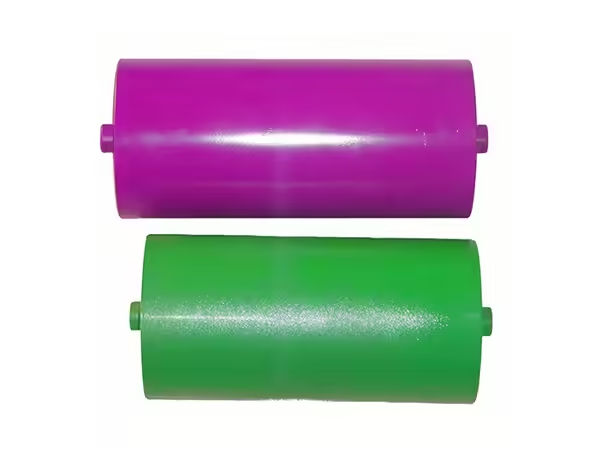
A conveyor belt continuously travels along a defined route while carrying bulk material or other loads. The idlers installed along this route create a series of rotating support points that prevent the belt from remaining unsupported across long distances.
As the belt passes over each roller, the roller shell rotates while its shaft remains supported by the frame. Bearings reduce resistance between the rotating shell and stationary shaft, while sealing components help protect the internal bearing area from contamination.
The forces acting on the belt are transferred through the roller shell, bearings, shaft, and supporting bracket into the conveyor structure. For this reason, the performance of conveyor rollers and idlers depends on the complete load path rather than on the outer tube alone.
Carrying Idlers on the Loaded Side
Carrying idlers support the conveyor belt while it transports material. Because this section carries both the belt and the conveyed load, its supporting geometry is particularly important.
Bulk-material conveyors frequently use troughing idlers rather than a completely flat arrangement. Several rollers are mounted at different angles so the belt develops a trough-shaped profile, helping keep loose material concentrated toward the center.
The rollers inside the set must work together. Their lengths, mounting angles, shaft positions, and bracket geometry determine how the belt is supported across its width.
If one roller is installed at a different height or angle, contact with the belt can become uneven even when the individual roller itself is dimensionally correct.
Why Troughing Geometry Matters
Troughing geometry increases the belt’s ability to contain bulk material, but it also changes how loads are distributed across the idler set.
The center roller supports the middle area of the belt, while the angled side rollers support the raised edges. Material distribution, belt tension, trough angle, roller spacing, and belt width all influence the forces acting on these components.
For this reason, conveyor rollers and idlers used in troughing arrangements should be specified as parts of one system.
Changing the length or angle of one roller without reviewing the complete set can alter the intended belt profile. Dimensional compatibility between rollers and brackets therefore matters just as much as the construction of the rollers themselves.
Return Idlers Support the Empty Belt
After transported material leaves the conveyor, the belt travels back toward the loading area. Return idlers support this lower section and control belt sag between structural supports.
Although the bulk load has been removed, return rollers can still operate under difficult conditions. Dust and residual material may remain attached to the belt surface and can be transferred repeatedly onto the rollers.
Return-side geometry also affects belt alignment. A damaged bracket or incorrectly positioned roller can change the contact relationship between the belt and supporting structure.
For this reason, return idlers should not simply be treated as less important versions of carrying rollers. Their specification and maintenance should correspond with the operating conditions found along the return path.
Parallel Rollers and Flat Belt Support
Parallel rollers can be used where the conveyor belt needs a relatively flat supporting surface. Depending on the system design, they may operate in upper or lower positions.
The existing product range includes parallel and other conveyor idler configurations, demonstrating that roller geometry needs to be matched with its actual belt-support function.
Parallel rollers still require correct shaft dimensions, bearings, seals, tube geometry, and mounting alignment. Their simpler installation geometry does not eliminate the need for dimensional consistency.
In long conveyor systems, many parallel rollers may operate consecutively, so small differences in mounting or rotational resistance can become more noticeable when repeated across an entire section.
Buffer Rollers in Loading Areas
Loading zones experience operating conditions different from those of normal carrying sections because material may fall onto the belt and generate dynamic impact.
Buffer rollers are specifically designed for these locations. Their structure helps reduce the effect of impact transmitted through the belt to the supporting components.
The need for buffer rollers depends on material characteristics, drop height, loading arrangement, belt structure, and the mechanical design of the conveyor.
This provides another clear example of why conveyor rollers and idlers should be selected according to position. A standard carrying roller may work reliably along a stable conveyor section but may not be the correct structure for an impact-sensitive loading area.
Conveyor Roller Sets Combine Multiple Components
A conveyor roller set combines individual rollers with a supporting bracket that determines their position and angle.
The conveyor roller set therefore needs to be evaluated as a complete assembly rather than as several unrelated rollers. The bracket establishes the geometric relationship between the individual rotating components and ultimately determines the shape in which the belt is supported.
For troughing arrangements, the angle of the side rollers is particularly important. For flat or return configurations, bracket dimensions still determine shaft position and belt height.
A high-quality individual roller cannot correct a poorly aligned frame, which is why roller manufacturing accuracy and idler-frame geometry need to work together.
Roller Diameter and Idler Function
Roller diameter influences rotational geometry, internal bearing arrangement, shaft structure, and the relationship between the roller and surrounding conveyor frame.
The current Conveyor Rollers range includes multiple diameters from approximately 60 mm through 219 mm. Different diameters can be combined with different lengths and internal structures according to the application.
However, roller diameter should not be selected independently from idler function. The carrying load, belt width, roller spacing, shaft dimensions, bearing configuration, installation position, and conveyor structure all affect the final requirement.
A larger diameter is therefore not automatically the correct solution. It needs to fit the complete mechanical system.
Roller Length Depends on Idler Arrangement
Roller length is strongly connected with belt width and the number of rollers used within each idler set.
A flat return roller may extend across a substantial portion of the belt width, while a troughing set divides belt support among several shorter rollers.
This means two conveyors using the same belt width can require different individual roller lengths if their idler arrangements are different.
Engineers should therefore identify the complete support geometry before defining roller length. The mounting width, shaft projection, bracket position, and belt contact area all need to correspond with one another.
This relationship becomes especially important when replacing existing rollers where the surrounding idler frame will remain unchanged.
Shaft Geometry Connects Rollers to the Idler Frame
The shaft creates the mechanical connection between the rotating roller and stationary idler bracket.
Its overall length, diameter, and end geometry determine how the roller sits within the supporting structure. Depending on the installation, shaft ends may contain flats, grooves, or other machined features.
Corresponding features at opposite ends need to remain accurately positioned because they establish the relationship between the roller and frame.
For repeated production, shaft machining consistency becomes particularly important. A batch of rollers with varying shaft-end geometry can create installation differences even when every roller tube has the correct length and diameter.
Bearings Control Roller Rotation
Bearings allow the roller shell to rotate relative to the fixed shaft. Their dimensions and positioning therefore affect the internal geometry of the complete idler roller.
Bearing selection should match roller diameter, shaft size, load requirements, housing structure, and sealing arrangement. These parameters are connected, so changing one component can require adjustments elsewhere in the assembly.
A bearing should not be evaluated only by its designation. Correct installation and alignment also matter because a suitable bearing positioned incorrectly can still create abnormal rotational behavior.
In large belt conveyor systems, maintaining similar bearing and assembly conditions across many rollers supports more consistent operation.
Bearing Housings Maintain Alignment
Bearing housings position and support the bearings inside the roller shell. Their geometry influences the relationship between the shaft and rotating tube.
If bearing housings at opposite ends are not located around a common axis, the completed roller can develop rotational variation even when the individual components meet their own dimensional requirements.
Housing position therefore forms an important link between manufacturing accuracy and field performance.
This is another reason why conveyor rollers and idlers should be evaluated beyond external dimensions. Much of the geometry that determines roller rotation is located inside the component and cannot be judged from the tube surface alone.
Sealing Is Critical in Industrial Idlers
Industrial conveyors frequently operate where dust, moisture, and fine particles are present around the roller ends.
Sealing systems create a protective path around the bearing chamber and reduce the ability of contaminants to reach sensitive internal components. Different roller structures can use different sealing arrangements depending on bearing housing geometry and environmental requirements.
Mining, quarrying, cement, and material-yard applications may require particular attention to sealing because contamination can occur continuously.
A suitable seal still needs correct dimensional compatibility with the shaft, bearing, and housing. Sealing should therefore be designed as part of the complete roller structure rather than added independently.
Conveyor Rollers and Idlers in Mining
Mining conveyors often transport coal, ore, and other bulk materials over long distances and through environments containing dust, moisture, vibration, and abrasive particles.
Carrying idlers support significant material loads, while return rollers operate beneath a belt that may still contain attached material. Loading zones can require buffer structures because falling bulk material introduces additional dynamic forces.
The conveyor may therefore use several different roller and idler configurations within the same installation.
Selecting components according to each position allows the mechanical structure to reflect the actual working conditions rather than relying on one universal roller design throughout the system.
Conveyor Rollers and Idlers in Quarrying
Quarry conveyors move stone and aggregate between crushers, screens, storage areas, and transfer points. The operating environment can include impact, abrasive particles, vibration, and significant dust.
The roller configuration near the loading point may therefore differ from one farther along a stable carrying section.
Idler alignment also deserves attention because material buildup around brackets can gradually change the position of supporting components.
For quarry applications, reliable operation depends on combining suitable roller construction with regular inspection of the complete idler assembly and surrounding conveyor structure.
Conveyor Rollers and Idlers in Cement Plants
Fine dust is a major consideration around many cement conveyor systems. Material can accumulate around roller ends, brackets, and sealing areas even when the conveyor continues operating normally.
Bearing protection therefore becomes an important part of roller specification. Sealing structures need to match the shaft, housing, and environmental conditions, while maintenance should monitor contamination around the roller ends.
The mechanical support function remains equally important. Carrying, return, and other idler positions should maintain the required belt geometry while providing stable rotation throughout the conveyor.
This combination of mechanical support and contamination control illustrates why idler design needs to address both structure and environment.
Roller Sets and Load Distribution
In a multi-roller idler set, conveyor load is distributed across several rotating components and then transferred into the supporting bracket.
Ideally, the belt contacts each roller according to the geometry intended by the conveyor design. If one roller sits at an incorrect position, the load distribution can change and increase contact pressure elsewhere.
Bracket deformation, improper installation, uneven material distribution, or inconsistent roller dimensions can all affect this relationship.
When one roller position experiences repeated problems, technicians should therefore inspect the full set rather than treating each failure as an isolated component issue.
Idler Spacing Influences Belt Support
The distance between successive idler sets determines how far the belt travels without direct roller support.
Spacing requirements depend on belt characteristics, conveyor load, material, structural design, and the specific operating section. Carrying-side spacing may differ from return-side spacing, while loading areas can require additional support.
Roller design and idler spacing should therefore be considered together.
A correctly specified roller may still experience abnormal loading if the conveyor structure places too much unsupported belt length between adjacent idlers.
Alignment Connects the Roller and Idler System
The rotating roller and supporting bracket need to maintain the intended relationship with the conveyor centerline.
If the bracket is twisted, the shaft is seated incorrectly, or structural supports are misaligned, belt contact can change even when the roller itself is manufactured correctly.
Alignment inspection should therefore examine several consecutive idler sets rather than one component in isolation.
This allows technicians to identify whether an abnormal belt path originates from a single roller or from gradual structural deviation along the conveyor.
Manufacturing Accuracy of Individual Rollers
The performance of an idler set depends partly on how consistently its individual rollers are manufactured.
Tube cutting establishes the basic roller length, shaft machining determines installation geometry, bearing housing positioning influences internal alignment, and assembly determines how these components ultimately interact.
When several rollers work side by side in one troughing set, dimensional differences can affect belt contact between neighboring components.
For this reason, manufacturing quality should focus on repeatable production across a batch rather than on one isolated finished roller.
Why Runout Matters
A roller with excessive runout does not maintain a consistent cylindrical path during rotation. Its outer surface repeatedly moves toward and away from the belt, changing the contact relationship during every revolution.
Runout can originate from tube geometry, bearing housing alignment, shaft position, assembly, welding, or damage during operation.
Within an idler set, one roller with significant runout can behave differently from surrounding components even if all are nominally the same size.
Final rotational inspection therefore provides useful information that individual part measurements alone cannot always reveal.
Terminology Matters When Defining Replacement Components
Maintenance teams sometimes use “idler,” “roller,” and “idler roller” interchangeably. While this is common in everyday communication, technical specifications should be more precise.
If only the individual cylindrical component needs replacement, roller diameter, body length, shaft geometry, bearing, seal, and mounting dimensions become critical.
If the complete idler set is being replaced, bracket geometry, roller angles, spacing, and installation dimensions must also be defined.
Clarifying which level of assembly is required reduces the chance of specifying a roller correctly while overlooking the structure into which it needs to fit.
How to Define Conveyor Rollers and Idlers Correctly
A practical specification should begin with conveyor position and operating function. Engineers can then define belt width, idler arrangement, roller diameter, roller length, shaft geometry, bearing structure, sealing system, material, and installation dimensions.
The operating environment should be added to this information because dust, moisture, impact, and conveyed material characteristics can influence internal component selection.
This creates a complete description of both the roller and the idler structure surrounding it.
It also allows manufacturing drawings and inspection requirements to use the same technical reference.
Common Mistake: Treating Roller and Idler as Completely Separate Products
Although roller and idler are different concepts, they are not independent systems. The roller performs the rotating support function inside the idler arrangement, while the idler frame determines how that roller contacts the belt.
Evaluating one without the other can therefore create specification problems.
A correctly manufactured roller can perform poorly if installed in an incorrectly aligned bracket, while a precisely manufactured frame cannot compensate for a roller with unsuitable shaft dimensions or internal bearing geometry.
The two need to be considered as connected elements of the same belt-support system.
Common Mistake: Selecting Only by Diameter
Roller diameter is easy to measure and is therefore often used as the first identification parameter. However, several rollers can share the same diameter while differing in length, shaft dimensions, bearing arrangement, seal structure, material, or installation function.
A replacement component should therefore be identified from a complete dimensional specification.
This is particularly important for conveyor rollers and idlers operating in existing industrial systems where brackets and mounting points are already fixed.
Common Mistake: Using One Idler Structure Everywhere
A conveyor contains different operating zones, and those areas do not necessarily require identical support structures.
Carrying sections need to support loaded belt, return sections handle the unloaded belt, loading areas may require buffering, and training positions can help manage belt guidance.
Using the same roller or idler configuration throughout the entire conveyor can ignore these differences.
A better approach is to divide the conveyor into functional sections and match the roller structure with the operating conditions at each position.
Inspection of Conveyor Rollers and Idlers
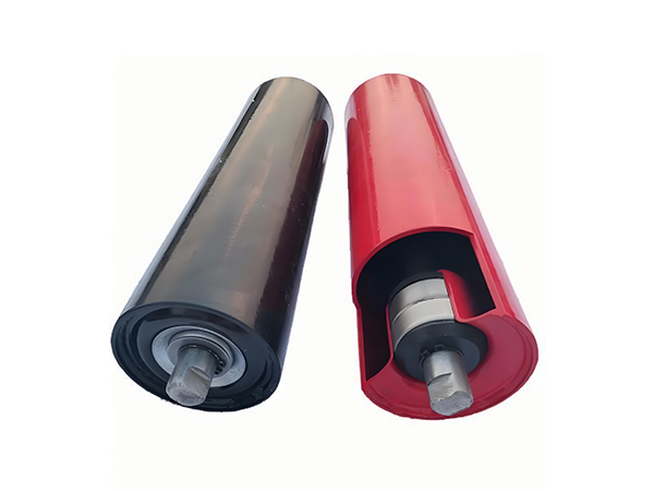
Routine inspection should consider both the rotating roller and the supporting idler structure.
Technicians can monitor roller rotation, noise, vibration, runout, seal condition, material buildup, shaft seating, bracket alignment, and belt contact. Comparing neighboring idlers also helps identify whether a problem is isolated or associated with a wider conveyor section.
Maintenance records can reveal repeated issues at the same position. When this happens, frame alignment, loading conditions, belt tracking, contamination, and idler geometry should be reviewed before another identical replacement is installed.
Conclusion
Conveyor rollers and idlers describe two closely connected parts of the same belt-support system. The roller is the cylindrical rotating component that contacts the belt, while an idler often describes the support function or the complete roller-and-bracket arrangement installed along the conveyor.
This distinction becomes important when defining carrying, return, buffer, parallel, and troughing arrangements. Roller diameter, length, shaft geometry, bearings, seals, and manufacturing accuracy determine how the individual component operates, while bracket position, installation angle, spacing, and alignment determine how those rollers work together.
For industrial belt conveyors, reliable support therefore depends on evaluating the roller and idler as one connected mechanical system. Understanding their relationship makes specification, installation, inspection, and maintenance more technically consistent across the complete conveyor.
FAQ
What is the difference between conveyor rollers and idlers?
A conveyor roller is normally the individual cylindrical component that rotates beneath the belt, while an idler can describe the non-driven support function or a complete roller-and-frame assembly. In a troughing idler set, several individual rollers work together on one bracket to create the required belt-support profile.
Are all conveyor rollers considered idler rollers?
Not every type of conveyor roller necessarily performs the same function, but rollers installed as non-driven supports beneath a belt are commonly referred to as idler rollers. Their specific role depends on whether they operate on the carrying side, return side, loading zone, or within a training or other idler arrangement.
What components are included in a conveyor idler set?
A conveyor idler set normally combines one or more rotating rollers with a stationary supporting bracket. The rollers themselves include tubes, shafts, bearings, bearing housings, and seals, while the bracket establishes their mounting position and angle so the complete assembly creates the required belt-support geometry.
How should conveyor rollers and idlers be selected?
Selection should consider belt width, conveyor position, load, roller diameter and length, shaft geometry, bearing arrangement, sealing structure, idler configuration, material, environmental conditions, roller spacing, and frame dimensions. These parameters should be evaluated together rather than selecting only by roller diameter.
Why is idler alignment important in a belt conveyor?
Idler alignment determines how the moving belt contacts the supporting rollers. Incorrect bracket position, shaft seating, or structural alignment can create uneven belt contact and contribute to tracking or loading problems. Inspection should therefore consider several neighboring idler sets as well as the condition of the individual roller.
 English
 French
 Spanish