

Table of Contents
Introduction
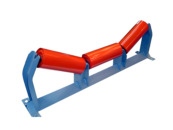
A conveyor roller is the result of several connected manufacturing stages rather than one isolated machining operation. Steel pipe must first be prepared to the required length, tube ends need controlled machining, roller shafts require their own features, bearing-related components must be assembled in alignment, and welding or final machining may be required before inspection.
A conveyor roller production line organizes these operations into a coordinated manufacturing workflow. The objective is not simply to place several machines next to one another. Each process should deliver a workpiece with predictable dimensions and geometry to the next stage so that variation does not accumulate as the roller moves through production.
For manufacturers producing rollers repeatedly, this process-based approach is especially important. Tube cutting, double-end machining, shaft processing, bearing setting, welding, and inspection all influence the final rotational geometry of the roller. This guide explains how a conveyor roller production line can be structured around these real manufacturing stages and how individual machines work together to improve process consistency.
What Is a Conveyor Roller Production Line?
A conveyor roller production line is a coordinated group of machining and assembly processes used to transform raw tube, shaft material, bearings, housings, seals, and related components into finished conveyor rollers.
It should not be understood as one single machine. Instead, the production line combines specialized equipment for different operations. The existing conveyor roller processing workflow includes tube cutting, tube-end machining, roller shaft machining, bearing assembly, welding, and other dedicated roller-processing stages.
The exact configuration depends on the type of roller being manufactured. A steel conveyor roller and an HDPE roller, for example, can require different machining routes even though both belong to the same broader roller manufacturing system.
A well-planned conveyor roller production line therefore begins with the finished roller drawing and works backward to determine which operations are required.
Why Roller Production Should Be Planned as a Complete Process
Manufacturing problems often appear at one stage even though their actual cause began earlier.
For example, inconsistent bearing assembly may originate from tube-end dimensions rather than from the pressing machine. Welding variation may result from poor component positioning before the roller reaches the welding station. Shaft installation problems can begin with incorrect milling or grooving.
This is why every stage of a conveyor roller production line should be connected through measurable process requirements.
Instead of asking whether each individual machine operates correctly, manufacturers should also ask whether the output from one machine provides the correct input for the next.
That relationship is what turns separate pieces of equipment into a controlled production line.
Typical Conveyor Roller Production Flow
A steel roller manufacturing process can be organized into several major stages.
| Production Stage | Main Operation | Purpose |
|---|---|---|
| Raw material preparation | Steel tube and shaft preparation | Establish starting material |
| Tube cutting | Cut roller shell blanks | Control initial shell length |
| Tube-end machining | Process both tube ends | Prepare bearing housing area |
| Shaft machining | Mill flats or grooves | Create mounting and assembly features |
| Shaft-end preparation | Flat, chamfer, center-hole work | Establish shaft-end geometry |
| Bearing assembly | Double-end hydraulic pressing | Position bearing-related components |
| Roller welding | Double-end circumferential welding | Join prepared components |
| Inspection | Dimensional and rotational checks | Confirm final consistency |
Not every roller follows exactly the same route. The production sequence should always be adapted to the actual roller construction.
Stage 1: Preparing Steel Pipe for Roller Shells
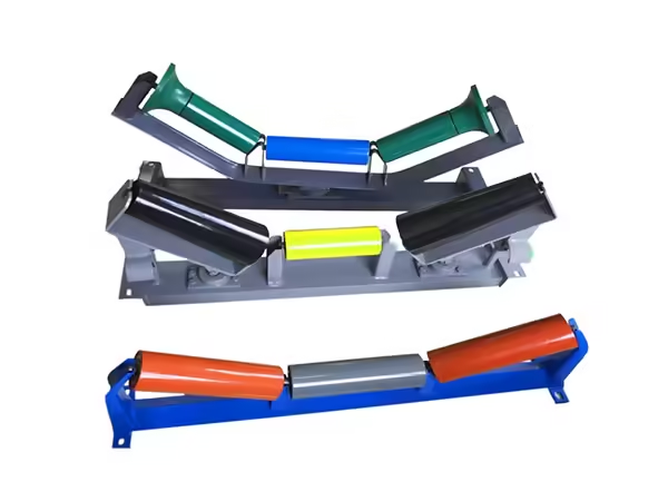
The roller shell begins as steel pipe. Before cutting starts, the raw material should be checked against the intended roller specification.
Important characteristics include outside diameter, wall thickness, straightness, material condition, and raw stock length.
Variation at this early stage can affect every later process. A pipe with poor straightness may be more difficult to feed accurately and can also influence the geometry of the finished roller shell.
For this reason, raw material inspection should form part of the conveyor roller production line rather than being treated as an activity outside manufacturing.
Once suitable material has been prepared, it can move into automatic cutting.
Stage 2: Automatic Tube Cutting
Tube cutting establishes the initial length of the roller shell.
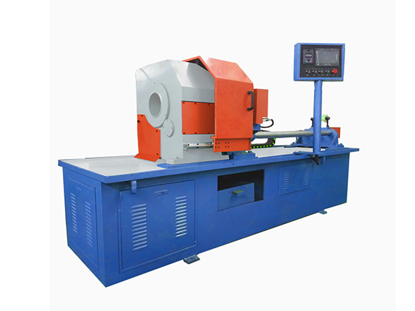
In the existing roller-processing equipment range, the automatic tube cutting process uses PLC control together with servo feeding, ball screws, and linear guides. The cutting structure keeps the tube stationary while the cutting tool rotates around it.
This arrangement is useful when long steel tubes are divided into repeated roller shell blanks.
Automatic length positioning reduces repeated manual measurement, while hydraulic or mechanical clamping keeps the tube stable during cutting.
The finished blank should provide a suitable starting condition for the next operation. Length, end-face condition, and burr formation should therefore be inspected rather than considering the operation complete as soon as the tube is separated.
Why Tube Cutting Accuracy Affects the Whole Line
A conveyor roller production line depends heavily on dimensional references.
If tube blanks vary substantially in length, the double-end machining stage receives inconsistent workpieces. The machining equipment may then remove different amounts of material from each roller shell.
This variation can continue into bearing assembly and welding.
For this reason, tube cutting should be evaluated not only by cutting speed but by how consistently it produces blanks that match downstream requirements.
The first completed blank after a setup change should be measured carefully, followed by periodic inspection during longer batches.
Stage 3: Double-End Roller Tube Machining
After cutting, the tube ends may require machining before bearing-related components can be installed.
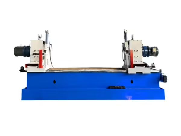
The Automatic Roller Double End Holes Lathe is designed specifically for processing steel pipe ends used in belt conveyor rollers. It uses quick mechanical clamping together with hydraulic cutter feeding.
An important feature of this structure is that the left and right feed cylinders can operate synchronously.
Processing both ends within one machine setup reduces the need to reverse the long cylindrical workpiece and establish a new machining reference for the second side.
This is particularly useful in batch roller production where the same tube geometry needs to be reproduced repeatedly.
Why Double-End Machining Supports Consistency
A conveyor roller naturally contains corresponding structures at opposite ends.
When these two areas are machined independently, every additional setup introduces another opportunity for positioning variation.
Double-end machining allows both sides to remain referenced to the same machine and clamping structure.
This does not eliminate the need for accurate cutting or workpiece inspection, but it reduces unnecessary handling between corresponding operations.
The result is a more controlled transition from cut tube blank to prepared roller shell.
Stage 4: Roller Shaft Preparation
The roller shaft follows a separate manufacturing path from the tube.
Depending on the roller design, the shaft may require flats, through-flats, circlip grooves, chamfers, flat end faces, or center holes.
These features determine how the shaft interacts with bearings, retaining components, installation brackets, and the conveyor frame.
The roller manufacturing machinery range includes several dedicated machines for these shaft-processing operations rather than relying on one general-purpose machine for every feature.
This specialization makes it possible to establish process conditions around the actual geometry of conveyor roller shafts.
Double-End Flat Slot Milling
Some roller shafts require flat surfaces at both ends.
The Automatic Roller Shaft Double End Flat Slot Milling Machine is designed for this task. Its structure allows machining to take place at both ends of the shaft and can process multiple surfaces within the same setup.
This reduces repeated manual repositioning of the shaft.
For a conveyor roller production line, consistent flat geometry matters because these surfaces may determine how the finished roller fits into the conveyor support structure.
If corresponding flats are positioned differently from one shaft to another, installation consistency may be affected even when the roller shell itself is accurate.
Through-Flat Milling for Roller Shafts
Another shaft-processing requirement is through-flat machining.
The Automatic Conveyor Roller Shaft Double-End Through Flat Milling Machine uses a symmetrical double-spindle structure to process corresponding shaft features at both ends.
This type of operation should remain distinct from general milling terminology because the machine is designed around long roller shafts and their specific end geometry.
Within the production line, this stage is selected only when the finished roller drawing requires that type of shaft feature.
The purpose is therefore not to process every shaft in the same way, but to route each roller design through the correct machining sequence.
Circlip Groove Machining
Some conveyor roller shafts require retaining grooves.
The Conveyor Roller Shaft Circlip Grooving Machine is specialized equipment for machining circlip grooves at both ends of belt conveyor roller shafts.
The machine can process corresponding grooves within the same setup, reducing repeated handling between the two ends.
Groove geometry and location need to correspond with the retaining component used later in assembly.
If the groove position varies, the final retaining relationship can also vary. This is why shaft grooving should be treated as a precision production stage rather than a secondary finishing operation.
Flat Head, Chamfer, and Center Hole Processing
Roller shafts may also require controlled end preparation before assembly.
The Flat Head Chamfer Playing Center Hole Machine Tool can complete flat-head machining, chamfering, and center-hole processing on both ends. It uses PLC control and is designed for shaft diameters from approximately Φ20 to Φ40 mm and lengths from 280 to 2200 mm.
Combining these operations helps maintain a more consistent relationship between corresponding shaft ends.
Chamfering also removes sharp end geometry, while the flat surface and center hole create useful machining references depending on the shaft design.
This machine should be used only where these operations are required by the roller specification.
Why Shaft Processing Should Be Separated From Tube Processing
The roller tube and shaft perform different mechanical roles.
The tube becomes the rotating outer shell, while the shaft forms the fixed central support. Their machining requirements are therefore different.
Trying to treat both components as one general machining problem can make process planning less precise.
A conveyor roller production line works more effectively when tube operations and shaft operations are managed as separate manufacturing streams before the components meet during assembly.
This also makes inspection easier because variation can be traced back to either tube preparation or shaft preparation.
Stage 5: Bearing and Housing Preparation
Before final roller assembly, bearing housings, bearings, seals, and related components need to match the selected roller structure.
Housing geometry needs to correspond with the tube and bearing, while the bearing size needs to match the shaft. Sealing elements must also be compatible with the surrounding assembly.
These relationships should be confirmed before hydraulic pressing begins.
An automatic assembly machine cannot correct components that do not fit the intended geometry.
For this reason, the component-preparation stage is an important checkpoint within the conveyor roller production line.
Stage 6: Double-End Bearing Assembly
The Roller Double-End Automatic Setting Bearing Machine is designed specifically for conveyor roller assembly.
The machine uses hydraulic press-fitting and processes both sides of the roller during the same cycle. Manual loading provides flexibility for different roller specifications, while the hydraulic pressing movement standardizes the critical assembly stage.
The TY-220×2200 model supports roller diameters of approximately Φ76–219 mm and roller lengths from 200–2200 mm.
The listed coaxial deviation between the two pressing spindles is no more than 0.1 mm, illustrating how important alignment is during roller assembly.
Why Pressing Force Is Not the Only Assembly Factor
Hydraulic pressing provides the force needed to position components, but assembly quality depends on much more.
Incoming tube dimensions, shaft geometry, bearing housing position, bearing size, spindle alignment, workpiece support, and fixture condition all influence the result.
If assembly resistance suddenly changes, the first response should not automatically be to increase hydraulic pressure.
The incoming components should first be checked to determine whether a dimensional change has occurred earlier in the production line.
This prevents the pressing machine from being used to compensate for upstream manufacturing variation.
Stage 7: Conveyor Roller Welding
Many steel roller structures require circumferential welding after components have been positioned.
The Roller Double End Carbon Dioxide Arc Welding Machine is designed for cylindrical workpieces and can weld both ends during the same production cycle.
The machine uses automatic centering, pneumatic clamping, controlled rotation, and PLC-based sequencing.
For conveyor rollers, these features help maintain a consistent relationship between the workpiece and welding heads while corresponding joints are processed.
The TH-220×2200 model supports workpiece diameters from approximately Φ76 to Φ219 mm and lengths from 200 to 2200 mm.
Why Welding Depends on Upstream Accuracy
Welding cannot reliably correct an incorrectly assembled roller.
If tube-end machining, shaft geometry, or bearing-related component positions vary, the weld joint may appear in a different location relative to the welding heads.
Even when electrical welding parameters remain identical, the physical relationship between the machine and workpiece can change.
For this reason, welding should be considered one of the final controlled stages in a larger manufacturing chain.
Stable upstream machining creates stable welding conditions.
Gas-Shielded Welding in Roller Manufacturing
The roller welding equipment uses gas-shielded arc welding methods.
In gas metal arc welding, a consumable wire electrode is continuously fed while shielding gas protects the weld area from the surrounding atmosphere.
For cylindrical conveyor rollers, the workpiece can rotate while the welding heads remain in defined positions.
This makes circumferential welding easier to automate because workpiece rotation creates the required welding path.
The actual current, rotation, gas flow, and wire settings should correspond with the established welding procedure and roller construction.
HDPE Rollers Require a Different Machining Branch
Not every conveyor roller production line should follow the same route.
HDPE rollers require a different machining process from conventional steel roller shells.
The HDPE Roller Cylindrical Lathe is designed specifically to machine the outside diameter of HDPE rollers. It uses CNC-controlled feeding while the workpiece rotates and the tool performs axial and radial movement.
This equipment should therefore be understood as a separate production branch within a broader roller-manufacturing capability.
Manufacturers should build the line around the actual roller material rather than force steel and polymer roller designs through identical operations.
How to Balance Machine Capacity Across the Line
The performance of a conveyor roller production line depends on the relationship between its stages.
If tube cutting produces blanks much faster than tube-end machining can process them, material begins to accumulate between machines. If bearing assembly is faster than welding, assembled rollers may wait before the next operation.
Increasing the speed of one machine does not necessarily increase total line output.
Manufacturers should therefore compare effective cycle times across the complete process.
Machine loading, unloading, adjustment, inspection, tooling changes, and specification changes should all be included when evaluating production flow.
Avoiding Bottlenecks
A bottleneck is the production stage that limits the output of the complete manufacturing sequence.
In roller production, this may change depending on the specification being produced.
A roller requiring complex shaft machining may place more pressure on the shaft-processing section, while another product may be limited by assembly or welding.
Production data should therefore be evaluated by roller family rather than assuming one machine is always the bottleneck.
The purpose of line balancing is to create predictable movement between processes without excessive accumulation of unfinished workpieces.
Managing Different Roller Specifications
Conveyor roller manufacturers frequently process multiple diameters, lengths, shaft configurations, and bearing structures.
A flexible production line therefore needs a controlled method for changing specifications.
Machine settings, fixtures, shaft programs, support positions, pressing-head locations, and welding positions may all require adjustment.
Frequently produced roller types can benefit from documented setup records.
Instead of rebuilding every machine configuration from memory, operators can return to previously validated settings and then verify the first finished component before the batch continues.
First-Piece Inspection After Setup Changes
Every major specification change should be followed by additional inspection.
For tube cutting, this means confirming finished length and end-face condition. For shaft machining, feature position and dimensions should be checked. For assembly, bearing position and symmetry matter. Welding inspection should confirm joint location and visible continuity.
The first-piece process helps prevent one incorrect setup from being repeated across an entire production batch.
Once the machine setting has been confirmed, periodic inspection can monitor whether the process remains stable.
Building Quality Control Into the Production Line
Quality control works best when it is distributed across the process rather than concentrated only at the end.
If tube blanks are checked immediately after cutting, cutting problems can be corrected before those workpieces enter end machining.
If shaft dimensions are verified after milling or grooving, unsuitable shafts can be identified before bearing assembly.
This approach also makes root-cause analysis easier.
When a finished roller shows a problem, process records help identify which manufacturing stage first introduced the variation.
Final Roller Inspection
A completed conveyor roller can be evaluated through dimensional, rotational, and visual inspection according to the product requirements.
Important characteristics may include overall length, shaft-end geometry, component position, weld condition, roller rotation, and radial runout.
The exact inspection plan should correspond with the roller specification and intended application.
Final inspection confirms whether the complete conveyor roller production line has successfully maintained the geometry established across all individual stages.
It should therefore be viewed as validation of the entire process rather than only of the final machine.
Why Runout Is a Production-Line Issue
Roller runout can be influenced by several different processes.
Tube straightness, end machining, bearing housing position, shaft alignment, assembly, and welding can all contribute.
This means abnormal runout should not automatically be attributed to one operation.
Troubleshooting should move backward through the production process to determine where the dimensional relationship changed.
A well-documented production line makes this investigation easier because each stage has measurable outputs.
Preventive Maintenance Across Multiple Machines
A conveyor roller production line contains multiple mechanical, hydraulic, pneumatic, servo, and control systems.
Maintenance therefore needs to cover more than cutting tools.
Linear guides, ball screws, hydraulic cylinders, clamping systems, milling spindles, pressing heads, welding rotation systems, pneumatic components, sensors, and PLC-controlled movements all influence production consistency.
Maintenance intervals should reflect operating conditions and machine usage.
Changes in sound, vibration, positioning, cutting quality, hydraulic movement, or finished dimensions can provide early indications that a machine needs inspection.
Tooling Management
Cutting and machining tools gradually wear during production.
A worn tube-cutting tool can increase burr formation or change the finished face. Milling tool wear can affect shaft geometry. Worn chamfering tools can alter edge condition or machining consistency.
Tooling condition should therefore be monitored through both operating time and workpiece inspection.
Replacing or adjusting tooling before major quality changes appear supports more stable production.
This is particularly important in batch manufacturing because one deteriorating tool can influence many components before the variation becomes obvious.
Workpiece Handling Between Machines
Production flow also depends on how components move from one stage to another.
Long tubes, roller shells, and shafts should be supported in a way that avoids unnecessary damage or deformation.
Machined surfaces and prepared shaft features should also be protected during handling.
A conveyor roller production line can use automatic, semi-automatic, or manual transfer depending on manufacturing scale, but the handling method should preserve the dimensional condition established by the previous operation.
Efficient machining provides little benefit if workpieces are damaged between processes.
When Automation Is Most Useful
Automation provides the greatest benefit when it controls repetitive processes that already have stable inputs.
Automatic feeding is effective when raw tubes have predictable dimensions. Double-end machining works best when blanks have consistent starting lengths. Hydraulic bearing pressing becomes more repeatable when mating components have controlled tolerances.
This illustrates an important principle:
Automation does not replace process control. It reproduces the process more consistently.
Manufacturers should therefore stabilize materials, tooling, fixtures, and inspection before expecting automation alone to solve production variation.
Designing a Conveyor Roller Production Line Around the Product
The finished roller drawing should remain the starting point for line design.
Manufacturers should identify tube material, outside diameter, wall thickness, roller length, shaft dimensions, shaft-end features, bearing structure, housing design, sealing system, welded joints, and inspection requirements.
The required machines can then be selected according to these operations.
This prevents unnecessary equipment from being added simply because it is commonly associated with roller manufacturing.
A production line should contain the processes required by the actual roller family.
Steel Roller and HDPE Roller Routes Should Be Planned Separately
Steel and HDPE rollers illustrate why one universal production sequence is not appropriate.
Steel rollers may require tube cutting, tube-end machining, bearing housing assembly, and welding.
HDPE rollers can require cylindrical turning of the polymer roller body and different assembly considerations.
The production layout can share some shaft-processing and inspection resources, but material-specific machining should remain distinct.
Planning these routes separately helps manufacturers avoid creating unnecessary operations.
Improving an Existing Roller Production Line
Improvement should begin with production data rather than adding equipment immediately.
Manufacturers can examine where workpieces accumulate, which stages require repeated adjustment, where dimensional variation first appears, and which machines create the longest interruptions during specification changes.
The most effective improvement may be better fixtures, more consistent upstream material, standardized setups, tooling management, or inspection procedures rather than an additional machine.
Once the actual limitation has been identified, automation or equipment changes can be applied more precisely.
Conveyor Roller Production Line Integration
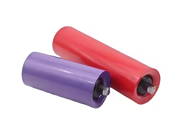
An integrated line does not necessarily mean every machine is physically connected through automatic transfer.
Integration can also mean that machines share common dimensional references, production records, process requirements, and inspection standards.
For example, the cutting stage knows the blank length required by tube-end machining. Shaft processing follows the dimensions required by assembly. The welding stage receives rollers whose joints appear in a predictable location.
This process integration is what creates manufacturing consistency.
The machines become parts of one production system because their outputs and inputs are deliberately coordinated.
Conclusion
A conveyor roller production line transforms raw tube, shaft material, bearings, housings, seals, and related components into finished rollers through a sequence of specialized manufacturing operations.
The process can include automatic tube cutting, double-end tube machining, flat or through-flat shaft milling, circlip groove processing, shaft-end chamfering and center-hole preparation, hydraulic bearing setting, double-end welding, and final inspection. HDPE rollers can follow a separate machining branch using cylindrical turning equipment.
The effectiveness of the line depends on how well these operations connect. Stable output from one machine creates predictable input for the next, while dimensional variation introduced early in production can continue through assembly and welding.
For this reason, successful roller manufacturing should focus on process coordination, first-piece inspection, tooling condition, machine maintenance, balanced capacity, and final dimensional control. A well-structured conveyor roller production line is not simply a collection of machines—it is a connected manufacturing system built around the geometry of the finished roller.
FAQ
What machines are used in a conveyor roller production line?
A conveyor roller production line can include automatic tube cutting equipment, double-end tube machining machines, roller shaft flat milling and grooving equipment, shaft-end processing machines, hydraulic bearing-setting equipment, double-end roller welding machines, and inspection stations. The exact combination depends on the roller design.
Does every conveyor roller need the same production process?
No. The manufacturing route depends on roller material, tube structure, shaft geometry, bearing housing, sealing system, and assembly design. Steel rollers and HDPE rollers can require different machining stages, while different shaft designs may need flat milling, through-flat processing, circlip grooves, or other features.
Why is double-end machining useful in roller production?
Conveyor rollers and their shafts often contain corresponding features at both ends. Double-end equipment can process these areas while the workpiece remains referenced within one machine setup. This reduces repeated repositioning and helps maintain a more consistent relationship between opposite ends during batch manufacturing.
How can manufacturers reduce variation across a roller production line?
Variation can be reduced by controlling raw materials, validating the first workpiece after setup changes, monitoring cutting and machining tools, maintaining fixtures and machine alignment, inspecting dimensions after critical stages, and ensuring each process delivers predictable components to the next operation.
How should a conveyor roller production line be planned?
Planning should begin with the finished roller drawing. Tube dimensions, shaft features, bearings, housings, seals, welded areas, roller material, and inspection requirements should first be defined. The necessary cutting, machining, assembly, welding, and inspection equipment can then be arranged around the actual production route.
 English
 French
 Spanish