
Tabla de contenido
Introducción
La soldadura es una etapa importante en la fabricación de muchas estructuras de rodillos transportadores. Una vez preparados el tubo del rodillo, el eje, la carcasa del rodamiento y los componentes relacionados, el proceso de soldadura debe mantener una relación estable entre la posición de la pieza de trabajo, la ubicación de la junta, la rotación, los parámetros de soldadura y las condiciones de blindaje. Cuando los rodillos se producen repetidamente en lotes, las variaciones en el posicionamiento manual pueden hacer que esta etapa sea más difícil de controlar.
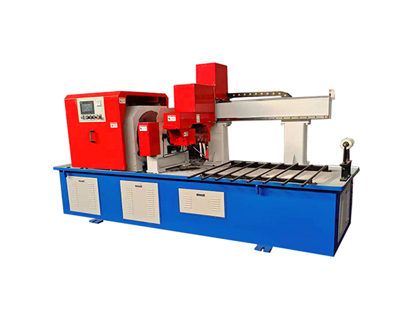
Una máquina de soldadura automática proporciona un enfoque más estructurado al coordinar la lógica de sujeción, centrado, rotación, movimiento de soldadura y control de la pieza de trabajo dentro de un ciclo operativo definido. Para la fabricación de rodillos transportadores, una configuración de doble extremo es particularmente útil porque las uniones correspondientes en ambos extremos de la pieza de trabajo cilíndrica se pueden procesar dentro de la misma configuración de máquina.
Este artículo explica cómo funcionan los equipos de soldadura automática en la producción de rodillos transportadores, por qué son importantes el centrado y la rotación de las piezas de trabajo, cómo el control PLC admite el funcionamiento repetible y qué deben evaluar los fabricantes al integrar equipos de soldadura con mecanizado ascendente e inspección posterior.
¿qué es una máquina de soldar automática?
Una máquina de soldar automática es un equipo industrial que realiza operaciones de soldadura seleccionadas mediante un movimiento mecánico controlado y una secuencia operativa predefinida. Dependiendo del diseño, la máquina puede controlar el posicionamiento de la pieza de trabajo, la sujeción, la rotación, el movimiento del cabezal de soldadura, el suministro de gas de protección y otras funciones requeridas durante el ciclo de soldadura.
En la producción de rodillos transportadores, la máquina necesita acomodar piezas de trabajo cilíndricas largas en lugar de láminas planas o estructuras irregulares. Esto crea requisitos específicos para la alineación central, la rotación, el soporte y el procesamiento simultáneo en extremos opuestos.
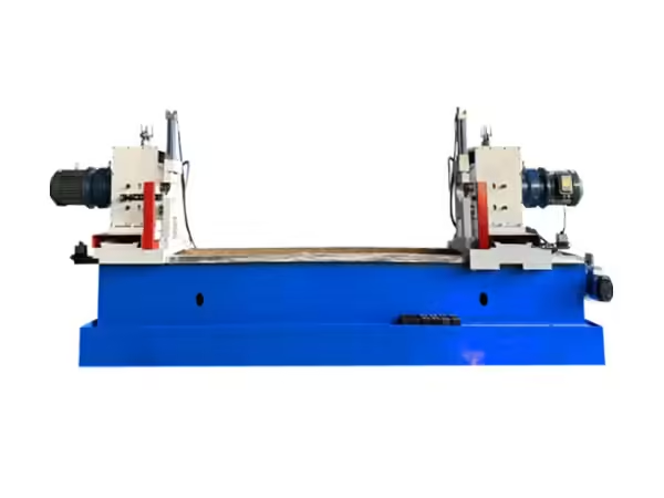
Pentru producție de roletor transportador, equipos de soldadura automática de doble extremo puede integrar centrado automático, sujeción neumática, soldadura simultánea en ambos extremos y control basado en PLC en un proceso coordinado para piezas de trabajo cilíndricas repetitivas.
Esta estructura especializada lo distingue de una estación de soldadura de uso general. El objetivo es organizar una tarea repetida de soldadura con rodillos alrededor de un ciclo de máquina controlado en lugar de reposicionar y alinear cada pieza de trabajo de forma independiente.
Por qué la soldadura de rodillos transportadores requiere un posicionamiento constante
Un rodillo transportador es rotacionalmente simétrico alrededor de su eje central. Esto significa que la relación entre el tubo del rodillo, los componentes relacionados con el rodamiento y las áreas soldadas debe permanecer consistente alrededor de la circunferencia.
Si una pieza de trabajo no está centrada correctamente antes de que comience la soldadura, la distancia entre el punto de soldadura y el eje de rotación puede variar a medida que gira el rodillo. Esto puede hacer que sea más difícil mantener una trayectoria de soldadura uniforme.
Por lo tanto, el posicionamiento de la pieza de trabajo se convierte en una de las funciones más importantes de una máquina de soldar automática. Antes de que comience el ciclo de soldadura, el rodillo debe ubicarse dentro de una posición definida de la máquina y alinearse con el mecanismo de rotación.
El posicionamiento estable también mejora la repetibilidad del proceso. Cuando cada rodillo ingresa a la máquina usando el mismo método de carga y centrado, la operación de soldadura depende menos de la alineación manual repetida.
Para la fabricación por lotes, esto crea un proceso más claro que se puede reproducir en muchos conjuntos de rodillos similares.
Cómo funciona la soldadura automática
Aunque los diseños de las máquinas varían, un ciclo automático de soldadura de rodillos normalmente combina varias funciones mecánicas y de control.
Primero se carga la pieza de trabajo en la máquina y se coloca entre los componentes de soporte o de accionamiento. Luego, la máquina centra y sujeta el rodillo para reducir el movimiento no deseado durante la operación.
Una vez asegurado el rodillo, los cabezales de soldadura se colocan en las uniones requeridas. La pieza de trabajo gira a una velocidad controlada mientras se realiza la soldadura alrededor de la circunferencia. En una configuración de doble extremo, las uniones correspondientes se pueden soldar en ambos extremos durante el mismo ciclo.
Una vez completada la soldadura, se detiene la rotación, los cabezales de soldadura regresan y la pieza de trabajo puede liberarse para inspección u operaciones de fabricación posteriores.
| Escenario | Función de la máquina | Propósito principal |
|---|---|---|
| Cargando | El rodillo entra en posición de soldadura | Prepare la pieza de trabajo |
| Centrado | El eje de la pieza de trabajo está alineado | Establecer una rotación estable |
| Reprimición | El rodillo está asegurado | Limite el movimiento durante la soldadura |
| Configuración de soldadura | Los jefes pasan a la posición conjunta | Establecer la ubicación de la soldadura |
| Rotación | La pieza de trabajo gira a velocidad controlada | Mantener la trayectoria de soldadura circunferencial |
| Soldadura simultánea | Ambos extremos están procesados | Coordinar la soldadura repetida |
| Regresar | Reinicio de componentes de soldadura | Ciclo completo de la máquina |
| Inspección | Se comprueban la soldadura y el montaje | Verificar el proceso terminado |
La eficacia de esta secuencia depende de la configuración correcta, los componentes preparados, la rotación estable, los parámetros de soldadura adecuados y el mantenimiento rutinario de la máquina.
Soldadura de doble extremo para rodillos transportadores
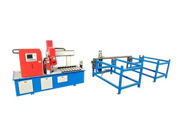
Una de las características más distintivas de la producción de rodillos es que a menudo se ubican juntas similares en ambos extremos de la pieza de trabajo.
Procesar cada extremo por separado requiere manipulación adicional de la pieza de trabajo. Es posible que sea necesario soltar, reposicionar, alinear nuevamente el rodillo y luego procesarlo en el extremo opuesto.
Una máquina de soldadura automática de doble extremo reduce estos pasos repetidos colocando dos posiciones de soldadura dentro de la misma estructura de la máquina. Una vez centrado y sujeto el rodillo, ambos extremos se pueden procesar como parte de un ciclo coordinado.
Este diseño se adapta bien a la producción de rodillos transportadores porque corresponde directamente a la naturaleza simétrica de la pieza de trabajo.
El beneficio no es simplemente un tiempo de procesamiento más corto. La soldadura de doble extremo también reduce la cantidad de configuraciones separadas necesarias para un rodillo, lo que puede ayudar a mantener una relación más consistente entre las juntas correspondientes.
Por qué es importante el centrado automático
El centrado establece la relación entre el eje del rodillo y el sistema rotacional de la máquina. Una pieza de trabajo cilíndrica necesita girar de manera predecible si se espera que el cabezal de soldadura siga una junta circunferencial consistente.
El centrado automático reduce la cantidad de ajustes manuales repetidos necesarios antes de cada ciclo de soldadura. Una vez cargada la pieza de trabajo, la estructura de la máquina ayuda a ubicarla en relación con el centro de trabajo definido.
Esto puede resultar particularmente útil al procesar rodillos en lotes repetidos porque no se requiere que los operadores establezcan una posición de soldadura completamente nueva para cada componente.
Sin embargo, la precisión del centrado todavía depende del estado de la pieza de trabajo. Si el tubo de rodillo o los componentes ensamblados están significativamente distorsionados o mecanizados incorrectamente, la máquina de soldar no puede compensar completamente esas variaciones aguas arriba.
Por lo tanto, el centrado automático debe funcionar junto con la preparación controlada del tubo, el mecanizado de los extremos y el montaje.
Soldadura por arco metálico a gas en equipos automáticos
La soldadura automática con rodillos puede utilizar procesos de soldadura por arco protegidos con gas. En soldadura por arco metálico a gas, se forma un arco eléctrico entre un electrodo de alambre consumible y la pieza de trabajo, mientras que el gas protector ayuda a proteger el área de soldadura de la contaminación atmosférica.
Este proceso se puede aplicar en sistemas semiautomáticos o automáticos, lo que lo hace adecuado para maquinaria donde la alimentación de alambre, la rotación de piezas de trabajo y el movimiento de soldadura deben operar como funciones coordinadas.
Para piezas de trabajo cilíndricas, como rodillos transportadores, la pieza de trabajo puede girar mientras la posición de soldadura permanece controlada. Esto permite que el proceso de soldadura siga la circunferencia de la junta sin necesidad de que un operador se mueva manualmente alrededor del rodillo completo.
El método de blindaje exacto y los parámetros de soldadura siempre deben corresponder al material de la pieza de trabajo, el diseño de la junta, el tipo de alambre, la configuración de la máquina y el procedimiento de soldadura establecido.
Control PLC y Automatización de Soldadura
El control PLC proporciona la lógica utilizada para coordinar una máquina de soldadura automática. En lugar de depender de comandos manuales independientes para cada operación, la máquina puede seguir una secuencia definida.
El controlador puede coordinar funciones como sujeción, centrado, rotación, inicio de soldadura, finalización de soldadura y retorno de la máquina. Esto hace que el proceso sea más fácil de repetir cuando se producen piezas de trabajo similares de forma continua.
El control PLC es especialmente útil cuando deben ocurrir varias acciones de la máquina en un orden específico. Por ejemplo, la soldadura no debe comenzar antes de que la pieza de trabajo esté correctamente asegurada y el retorno de la máquina debe ocurrir sólo después de que se haya completado la etapa de soldadura.
Sin embargo, la lógica de control por sí sola no puede crear un proceso de soldadura preciso. La alineación mecánica, el estado de los accesorios, la geometría del rodillo, la posición del cabezal de soldadura y la preparación de la pieza de trabajo también deben permanecer estables.
La automatización exitosa proviene de combinar un diseño mecánico confiable con un control consistente en lugar de depender únicamente del controlador.
Rotación de piezas de trabajo y uniformidad de soldadura
En la soldadura con rodillos, la propia pieza de trabajo puede girar mientras el cabezal de soldadura permanece colocado en la junta requerida. Este enfoque es muy adecuado para soldaduras circunferenciales.
La velocidad de rotación debe corresponderse con el proceso de soldadura. Si la pieza de trabajo gira demasiado rápido o demasiado lentamente en relación con los parámetros seleccionados, la condición de soldadura resultante puede cambiar.
Por lo tanto, la rotación estable pasa a formar parte del control del proceso. El sistema de accionamiento debe mantener un movimiento predecible durante el ciclo de soldadura en lugar de permitir una aceleración o variación irregular de la velocidad.
El eje de rotación también debe permanecer alineado con el rodillo. Una pieza de trabajo descentrada puede hacer que la posición de la junta se acerque y se aleje del cabezal de soldadura a medida que gira.
Esta es la razón por la que el centrado, la sujeción y la rotación deben evaluarse como una función integrada y no como tres características independientes de la máquina.
Sujeción neumática y estabilidad de la pieza de trabajo
Una pieza de trabajo debe permanecer colocada de forma segura mientras gira y mientras se lleva a cabo el proceso de soldadura. La sujeción neumática proporciona un método para sujetar el rodillo dentro de la máquina.
El sistema de sujeción debe proporcionar suficiente estabilidad sin interferir con la rotación o dañar la pieza de trabajo. También debería permitir cargar y soltar los rodillos en una secuencia de producción práctica.
Para una fabricación repetida, una sujeción constante ayuda a garantizar que cada rodillo comience el ciclo de soldadura desde una condición mecánica similar.
La fuerza de sujeción por sí sola no es la única consideración. La ubicación y geometría de los puntos de contacto también importan porque determinan cómo se soporta el rodillo.
Por lo tanto, la inspección rutinaria de abrazaderas, superficies de posicionamiento y componentes neumáticos es una parte importante para mantener un funcionamiento constante.
Hacer coincidir las dimensiones de la máquina con las de la pieza de
Los equipos de soldadura automática deben seleccionarse de acuerdo con las piezas de trabajo reales que se procesarán.
Las dimensiones importantes incluyen el diámetro del rodillo, la longitud total de la pieza de trabajo, la posición de la junta y la geometría de los componentes que se sueldan. Si la pieza de trabajo queda fuera del alcance práctico de la máquina, puede resultar difícil centrarla, soportarla y posicionarla correctamente con el cabezal de soldadura.
El modelo TH-220*2200 actual de Terok está diseñado alrededor de piezas de trabajo cilíndricas dentro de un rango definido de diámetro y longitud, lo que ilustra por qué el rango de trabajo de la máquina debe compararse directamente con los dibujos de rodillos antes de la configuración de producción.
Los fabricantes que producen varias especificaciones de rodillos también deberían considerar el ajuste entre tamaños. Cambiar las dimensiones de la pieza de trabajo puede afectar la posición del soporte, la posición del cabezal de soldadura, los ajustes de rotación y la sujeción.
Por lo tanto, es importante un sistema de ajuste práctico cuando una máquina necesita soportar múltiples modelos de rodillos.
Máquina de soldadura automática versus soldadura manual con rodillos
Tanto la soldadura manual como la automatizada tienen aplicaciones adecuadas, pero la producción repetida de rodillos transportadores crea requisitos de fabricación específicos.
La soldadura manual proporciona flexibilidad al operador y puede resultar práctica para trabajos especializados o producción de baja frecuencia. Sin embargo, cada pieza de trabajo puede requerir posicionamiento, alineación y movimiento manual repetidos del soplete.
Una máquina de soldadura automática desplaza más de estas acciones repetidas a una secuencia de máquina definida. La pieza de trabajo se centra, sujeta, gira y suelda en condiciones operativas establecidas.
Por lo tanto, la diferencia no es simplemente si una persona o una máquina realiza la soldadura. La mayor diferencia radica en la repetibilidad del proceso.
Para la fabricación de rodillos por lotes, reducir la variación innecesaria entre piezas de trabajo puede ser más importante que maximizar la velocidad de una operación de soldadura individual.
El mecanizado ascendente afecta directamente a la soldadura
La calidad de la soldadura no se puede separar de los componentes que ingresan a la estación de soldadura.
Si los tubos de rodillos tienen longitudes inconsistentes o extremos mal preparados, la posición de la junta puede variar entre piezas de trabajo. Si las carcasas de los cojinetes o los componentes relacionados no se colocan de manera consistente, la máquina de soldar puede encontrar diferentes geometrías de unión incluso cuando sus ajustes permanecen sin cambios.
Por lo tanto, el corte de tubos, el mecanizado de extremos, el procesamiento de ejes y el ensamblaje deben establecer una geometría estable de la pieza de trabajo antes de que comience la soldadura.
La etapa de soldadura está estrechamente relacionada con procesos ascendentes como corte de tubos, mecanizado de tubos de doble extremo, procesamiento de ejes, fraguado de rodamientos y soldadura de rodillos, por lo tanto, la consistencia de la producción depende de qué tan bien funcionen juntas estas operaciones antes de que la pieza de trabajo llegue a la inspección final.
Tratar estas operaciones como una secuencia de producción conectada facilita la resolución de problemas porque la variación se remonta a la etapa en la que aparece por primera vez.
La soldadura es una parte de la línea de producción de rodillos
Una máquina de soldar automática no debe tratarse como una unidad de producción aislada. Su eficiencia depende en parte de cómo llegan las piezas de trabajo y de dónde se mueven después de soldarlas.
Un flujo de trabajo típico puede implicar:
Preparación de tubos → mecanizado de extremos de tubos → procesamiento de ejes → ensamblaje de componentes → soldadura → inspección
Cada proceso debe proporcionar una pieza de trabajo que esté lista para la siguiente operación.
Si la capacidad de soldadura es mucho mayor que la capacidad de mecanizado aguas arriba, el equipo de soldadura puede pasar mucho tiempo esperando piezas de trabajo. Si la soldadura se vuelve más lenta que el montaje, los componentes sin terminar pueden acumularse antes de la estación de soldadura.
Por lo tanto, la planificación de la producción debe considerar el equilibrio del proceso en lugar de la capacidad máxima de una máquina.
Este enfoque es particularmente útil cuando se construye gradualmente un sistema de producción de rodillos transportadores más automatizado.
Factores clave a la hora de evaluar equipos de soldadura automática
Los fabricantes deben evaluar una máquina de soldar automática según la pieza de trabajo y el proceso y no sólo según las características generales de automatización.
Varios factores merecen especial atención:
| Factor de evaluare | Por qué es importante |
|---|---|
| Diámetro de la pieza de trabajo | Determina compatibilidad con soportes y sistema de rotación |
| Longitud de la pieza de trabajo | Afecta el ajuste y posicionamiento de la máquina |
| Método de centrado | Influye en la alineación rotacional |
| Sistema de sujeción | Estabiliza la pieza de trabajo durante la soldadura |
| Control de rotación | Soporta un movimiento circunferencial consistente |
| Proceso de soldadura | Debe coincidir con el material y la estructura de la junta |
| Control PLC | Coordina la secuencia operativa de la máquina |
| Capacidad de doble extremo | Admite procesamiento simultáneo de extremos de rodillos |
| Método de ajuste | Importante para múltiples especificaciones de rodillos |
| Acceso de mantenimiento | Admite un funcionamiento estable a largo plazo |
La mejor configuración depende de cómo interactúan estos factores con el proceso real de fabricación de rodillos.
Cómo la soldadura automática respalda la fabricación por lotes
La producción por lotes requiere que se repita el mismo proceso en muchas piezas de trabajo. Por lo tanto, pequeñas variaciones en la configuración pueden volverse más significativas a lo largo de una larga producción.
La soldadura automática crea una secuencia estructurada que se puede reutilizar de un rodillo al siguiente. Los operadores aún necesitan cargar piezas de trabajo, verificar el estado de la máquina, ajustar la configuración cuando cambian las especificaciones e inspeccionar la soldadura terminada, pero el ciclo de soldadura del núcleo sigue un proceso mecánico y de control definido.
Esta división del trabajo puede facilitar la estandarización de la producción.
También crea documentación de proceso más clara. Los fabricantes pueden definir condiciones de configuración para una especificación de rodillo particular y utilizar esas condiciones nuevamente cuando el mismo producto regrese a producción.
Por lo tanto, la repetibilidad es una de las razones más importantes para aplicar la automatización de la soldadura a la fabricación estandarizada de rodillos transportadores.
Gestión de diferentes especificaciones de rodillos
Un fabricante puede producir rodillos con diferentes diámetros, longitudes, estructuras de juntas o disposiciones de rodamientos. El equipo de soldadura necesita suficiente flexibilidad para adaptarse a la gama prevista.
Antes de cambiar las especificaciones, es posible que los operadores necesiten ajustar los soportes de las piezas de trabajo, las posiciones de los cabezales de soldadura, los ajustes de rotación y las ubicaciones de sujeción.
Estos cambios deben seguir un procedimiento de configuración definido en lugar de depender exclusivamente de la experiencia del operador.
Una práctica útil es registrar configuraciones de máquinas validadas para especificaciones de rodillos producidas con frecuencia. Esto hace que la configuración posterior sea más sistemática y reduce los ajustes repetidos de las pruebas.
Después de un cambio de especificación, la primera pieza de trabajo terminada también debe recibir una inspección cuidadosa antes de que continúe el lote completo.
Los parámetros de soldadura necesitan control de proceso
El funcionamiento automático no elimina la necesidad de establecer parámetros de soldadura adecuados. La corriente de soldadura, el voltaje, el flujo de gas de protección, la rotación de la pieza de trabajo, la alimentación de cables y la geometría de la junta interactúan durante el proceso de soldadura.
Estos ajustes deben establecerse de acuerdo con el material, el procedimiento de soldadura, el alambre, el método de blindaje y el diseño de la pieza de trabajo.
Una vez definidos los parámetros adecuados, la automatización ayuda a reproducir la secuencia mecánica asociada con esas configuraciones.
Los operadores aún deben monitorear la apariencia de la soldadura y el comportamiento de la máquina durante la producción. Los cambios en la condición del cable, la entrega del blindaje, el ajuste de los componentes o la condición del equipo pueden influir en el proceso incluso cuando el controlador continúa usando el mismo programa.
Por lo tanto, la soldadura automática debe entenderse como una repetición controlada y no como una operación desatendida.
Causas comunes de soldadura de rodillos inconsistente
Cuando los resultados de la soldadura varían entre rodillos, la máquina de soldar en sí es sólo una fuente posible.
Las dimensiones de la pieza de trabajo pueden diferir debido al mecanizado aguas arriba. Es posible que los componentes se hayan ensamblado en diferentes posiciones. Es posible que el rodillo no esté completamente centrado o correctamente sujeto. Es posible que la posición del cabezal de soldadura haya cambiado o que el sistema rotacional requiera inspección.
También se deben comprobar las condiciones de blindaje y alimentación de cables.
Un enfoque estructurado de resolución de problemas puede separar estos factores:
Primero verifique las dimensiones y el ensamblaje de la pieza de trabajo.
Luego verifique el centrado y la sujeción.
A continuación, confirme la posición y la rotación del cabezal de soldadura.
Finalmente revise los parámetros de soldadura, la entrega del blindaje y el estado de la máquina.
Seguir el proceso en secuencia hace que sea más fácil identificar la fuente real de variación en lugar de cambiar repetidamente la configuración de soldadura.
Inspección después de la soldadura automática
La inspección debe realizarse antes de que el rodillo avance en la producción.
Los requisitos exactos dependen del diseño del rodillo y del procedimiento de soldadura, pero la inspección puede incluir continuidad de la soldadura, condición de la superficie visible, posición de la junta, simetría entre ambos extremos y la relación entre los componentes soldados.
La rotación del rodillo y el estado general del montaje también pueden comprobarse después de la soldadura si esas características son relevantes para la etapa de producción.
Cuando se utiliza soldadura de doble extremo, comparar los dos extremos puede proporcionar información útil sobre la configuración de la máquina. Las diferencias repetidas entre los lados izquierdo y derecho pueden indicar un problema de posicionamiento o de equipo que debe investigarse.
Los registros de inspección también proporcionan información útil para la configuración y el mantenimiento posteriores de la máquina.
Mantenimiento de una Máquina Soldadora Automática
El funcionamiento automático estable requiere atención rutinaria tanto a los componentes de soldadura como a los sistemas mecánicos.
Los dispositivos de sujeción, componentes rotacionales, mecanismos guía, sensores, sistemas neumáticos, conexiones eléctricas y posicionamiento de los cabezales de soldadura deben comprobarse de acuerdo con los requisitos de mantenimiento de la máquina.
Los componentes de alimentación de cables y el suministro de gas de protección también deben permanecer en condiciones apropiadas para el proceso de soldadura que se utiliza.
Los accesorios y superficies de contacto deben mantenerse limpios porque los residuos acumulados pueden influir en el posicionamiento de la pieza de trabajo.
También se debe observar el comportamiento de la máquina a lo largo del tiempo. Los cambios en la rotación, el movimiento inusual, la sujeción irregular o el comportamiento inconsistente del ciclo pueden proporcionar señales tempranas de que es necesaria una inspección.
Por lo tanto, el mantenimiento contribuye directamente a la repetibilidad del proceso en lugar de servir únicamente como mantenimiento del equipo.
¿cuándo es adecuada la soldadura automática para la producción de rodillos?
La soldadura automática es particularmente relevante cuando los fabricantes procesan repetidamente piezas de trabajo cilíndricas con ubicaciones de unión similares.
Los rodillos transportadores se ajustan a este patrón porque comúnmente utilizan estructuras simétricas y áreas de soldadura circunferenciales. La maquinaria de doble extremo puede aprovechar aún más esta geometría procesando ambos extremos en una sola configuración.
El equipo es especialmente útil cuando los fabricantes desean reducir el posicionamiento manual repetido y establecer una secuencia de soldadura más estandarizada en todos los lotes de producción.
Sin embargo, la decisión aún debería reflejar los requisitos reales de producción. La gama de rodillos, la variedad de productos, las condiciones de mecanizado ascendentes, el diseño disponible de la fábrica y los procesos circundantes influyen en la utilidad de la automatización.
Los resultados más sólidos se producen cuando la máquina de soldar resuelve un requisito de fabricación claramente identificado dentro del flujo de producción completo.
Construyendo un proceso de fabricación de rodillos más integrado
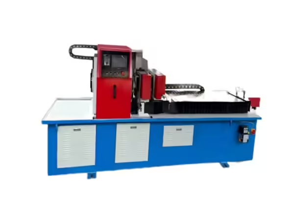
El mayor beneficio de una máquina de soldar automática aparece cuando se integra con las etapas de fabricación circundantes.
El corte constante del tubo le da a la carcasa del rodillo una dimensión inicial predecible. El procesamiento preciso de los extremos ayuda a establecer una geometría de unión repetible. El ensamblaje controlado posiciona los componentes correctamente antes de soldar. El centrado automatizado y la soldadura de doble extremo completan la operación de unión bajo un ciclo de máquina definido.
La inspección confirma si estos procesos conectados están produciendo el resultado deseado.
Cuando aparece un problema, esta estructura del proceso también facilita el análisis. En lugar de tratar la soldadura terminada como un resultado aislado, los fabricantes pueden examinar cada operación anterior y determinar dónde entró la variación por primera vez en la pieza de trabajo.
Este es un principio importante para desarrollar un sistema de producción de rodillos transportadores estable.
Conclusión
Una máquina de soldadura automática puede convertir la soldadura con rodillo transportador de una tarea manual altamente repetitiva a un proceso de fabricación definido. Al coordinar el centrado, la sujeción, la rotación de la pieza de trabajo, el movimiento de soldadura y el control del PLC, el equipo proporciona un enfoque estructurado para la producción de rodillos por lotes.
La soldadura de doble extremo es particularmente relevante para los rodillos transportadores porque corresponde a la estructura simétrica de la pieza de trabajo y reduce el posicionamiento repetido entre extremos opuestos.
Sin embargo, la automatización por sí sola no determina la consistencia de la soldadura. La preparación de los tubos, el mecanizado de los componentes, la precisión del montaje, la alineación de las piezas de trabajo, las condiciones de blindaje, los parámetros de soldadura, los accesorios y el mantenimiento contribuyen al resultado final.
Por lo tanto, los fabricantes deberían evaluar los equipos de soldadura automática como parte de una secuencia de producción completa. Cuando el mecanizado ascendente, la automatización de la soldadura y la inspección trabajan juntos, la producción de rodillos se vuelve más fácil de controlar y repetir en diferentes lotes de fabricación.
Preguntas frecuentes
¿para qué se utiliza una máquina de soldar automática en la producción de rodillos transportadores?
Se utiliza una máquina de soldadura automática para controlar operaciones repetidas de soldadura en conjuntos de rodillos. Puede coordinar el centrado, sujeción, rotación, soldadura y secuenciación de la máquina de la pieza de trabajo para crear un proceso de fabricación más consistente.
¿por qué la soldadura de doble extremo es adecuada para rodillos transportadores?
Los rodillos transportadores suelen contener juntas similares en ambos extremos. Una máquina de doble extremo puede procesar estas juntas dentro de una configuración, lo que reduce el reposicionamiento repetido de las piezas de trabajo y permite que ambas operaciones sigan un ciclo coordinado.
¿Qué hace el control PLC en una máquina de soldar automática?
El control PLC coordina la secuencia de funciones de la máquina. Dependiendo del diseño del equipo, esto puede incluir sujeción, rotación, inicio y finalización de la soldadura y retorno de la máquina.
¿por qué es importante el centrado automático para la soldadura con rodillos?
El centrado alinea la pieza de trabajo cilíndrica con el sistema rotacional. La alineación estable ayuda a mantener la junta circunferencial en una relación consistente con el cabezal de soldadura a medida que gira el rodillo.
¿Puede una máquina de soldar automática procesar diferentes tamaños de rodillos?
Esto depende del rango de trabajo diseñado por la máquina y del sistema de ajuste. El diámetro de la pieza de trabajo, la longitud, la posición de la junta, los soportes, la ubicación del cabezal de soldadura y la configuración de sujeción deben corresponder a las especificaciones previstas del rodillo.
 Spanish
  English
  French