
Table des matières
Introduction
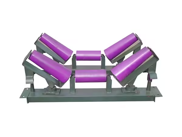
Un rouleau pour équipement de convoyeur peut sembler être un composant rotatif relativement simple, mais sa fiabilité de fonctionnement dépend d'une combinaison de charge, de géométrie, de support d'arbre, de performances de roulement, d'étanchéité, de précision de fabrication et de conditions d'installation. Dans un convoyeur de travail, le rouleau ne fonctionne pas indépendamment. Il interagit en permanence avec la bande, le matériau transporté, les rouleaux voisins, les supports de montage et le cadre du convoyeur, ce qui signifie que même une petite inadéquation dans une zone peut influencer les performances du système plus large.
Pour cette raison, la sélection des rouleaux ne doit pas commencer par le seul diamètre ou la longueur hors tout Deux rouleaux ayant des dimensions extérieures similaires peuvent se comporter très différemment si leur épaisseur de coque, la conception de l'arbre, la position du roulement, la structure du joint ou la géométrie de montage Un rouleau qui fonctionne de manière fiable dans une section de retour peut également être inadapté à une position de transport fortement chargée car les forces et les conditions environnementales ne sont pas les mêmes.
La façon la plus efficace de spécifier un rouleau pour les applications de convoyage est de commencer par la position de fonctionnement et de suivre la charge à travers l'ensemble complet Cela permet de déterminer ce que la coque doit supporter, comment les roulements transfèrent la force, comment l'arbre se connecte au cadre, et comment la précision de fabrication affecte la rotation Les sections suivantes examinent ces relations en détail et expliquent comment une spécification plus complète peut améliorer la fiabilité, la compatibilité de remplacement et les performances à long terme du convoyeur.
La fonction d'un rouleau dépend de la position de son convoyeur
UN système de convoyage peut contenir de nombreux rouleaux, mais ils ne fonctionnent pas tous dans les mêmes conditions L'emplacement du rouleau détermine le type de charge qu'il reçoit, comment il interagit avec la bande, et quels facteurs environnementaux sont les plus importants.
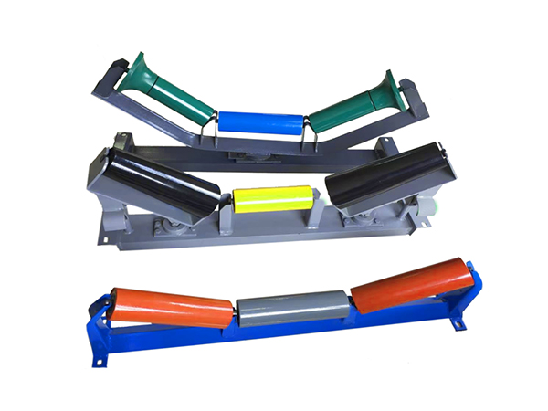
Les rouleaux porteurs fonctionnent sous la bande chargée et supportent le poids combiné de la bande et du matériau transporté Leurs exigences structurelles sont donc fortement influencées par la charge du matériau, la largeur de la bande, l'espacement des rouleaux et la géométrie des rouleaux de renvoi supportent la bande après le déchargement du matériau, de sorte que leur condition de chargement direct est différente, bien qu'ils puissent rencontrer plus de report de matériau sur la surface de la bande.
Les rouleaux installés à proximité des zones de chargement connaissent un autre type de condition de fonctionnement Le matériau arrivant sur la courroie peut créer des forces dynamiques qui sont différentes de la charge relativement stable que l'on trouve le long des sections de transport normales Dans ces positions, la construction des rouleaux et les dispositions de support doivent tenir compte de l'impact ainsi que de la charge continue.
C'est pourquoi un rouleau pour équipement de convoyage devrait toujours être spécifié en fonction de sa position réelle La normalisation de chaque rouleau autour d'une construction peut simplifier l'achat, mais elle ne crée pas nécessairement la solution mécanique la plus appropriée pour chaque partie du convoyeur.
L’espacement des charges et des rouleaux doit être considéré ensemble
La quantité totale de matière sur un convoyeur n'agit pas sur un rouleau Elle est répartie sur plusieurs positions de support, ce qui signifie que l'espacement des rouleaux influence directement la charge subie par chaque composant.
Lorsque les rouleaux sont positionnés plus près les uns des autres, davantage de points d'appui sont disponibles sous une section donnée de la bande Un espacement plus large réduit le nombre de rouleaux partageant la même charge et peut également permettre un plus grand mouvement de la bande entre les supports L'espacement correct dépend donc des caractéristiques de la bande, du matériau transporté, de la géométrie du convoyeur et de la charge de fonctionnement.
Cette relation devient encore plus importante lorsque la répartition de la charge est irrégulière Le matériau en vrac peut ne pas rester parfaitement centré, et les conditions de fonctionnement changeantes peuvent créer une charge concentrée temporaire Une conception de rouleau basée uniquement sur une charge moyenne du système peut donc négliger les forces subies à des positions particulières.
Une spécification utile devrait tenir compte à la fois des conditions normales de fonctionnement et des changements réalistes dans la répartition des matériaux L'objectif n'est pas de rendre chaque rouleau inutilement lourd, mais de fournir une stabilité structurelle suffisante dans les conditions que le convoyeur subit réellement.
| Facteur d'application | Influence sur la conception des rouleaux |
|---|---|
| Largeur de ceinture | Affecte la longueur de travail du rouleau et la géométrie du support |
| Charge matérielle | Influence les exigences en matière de coque, d'arbre et de roulement |
| Espacement des rouleaux | Modifie la charge portée par chaque position de support |
| Vitesse du convoyeur | Influence le comportement au roulement et à la rotation |
| Méthode de chargement | Peut introduire des forces dynamiques ou d'impact |
| Position du rouleau | Détermine le transport, le retour ou le service spécialisé |
| Environnement opérationnel | Influence les exigences d’étanchéité et de surface |
Considérer ces facteurs ensemble fournit une base plus réaliste pour la sélection des rouleaux que d’utiliser un seul chiffre de charge nominale.
Le diamètre de la coque et l'épaisseur de la paroi ne définissent qu'une partie de la résistance du rouleau
La virole cylindrique reçoit le contact direct de la courroie et forme la principale structure visible d'un rouleau Son diamètre et son épaisseur de paroi sont donc importants, mais aucune des deux valeurs ne doit être considérée indépendamment.
Un diamètre de rouleau plus grand peut modifier la rigidité structurelle et fournir plus d'espace interne pour les roulements et autres composants Il modifie également la géométrie de contact entre le rouleau et la courroie Cependant, l'augmentation du diamètre n'améliore pas automatiquement la fiabilité si l'arbre, les roulements ou l'agencement de montage restent inadaptés à l'application.
L'épaisseur de paroi affecte la capacité de la coque à maintenir sa géométrie sous charge Une coque trop légère pour sa longueur de travail et son état de fonctionnement peut se déformer plus que prévu, tandis qu'une épaisseur de paroi excessive augmente la matière et la masse en rotation sans nécessairement améliorer la partie la plus faible de l'ensemble.
La longueur du rouleau modifie également l'état structurel Un long rouleau avec un diamètre et une épaisseur de paroi donnés se comporte différemment d'un rouleau court construit à partir du même tube car l'envergure non supportée entre les emplacements de roulement est différente.
Pour cette raison, la construction de rouleaux de convoyeur doit être considéré comme une combinaison de géométrie de coque, de support d'arbre, de roulements, de dimensions de montage et d'exigences d'application plutôt que comme un choix basé uniquement sur le diamètre extérieur.
La géométrie de l'arbre transfère la charge du rouleau dans le châssis du convoyeur
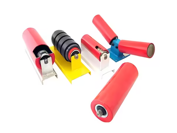
La coque du rouleau supporte la courroie, mais l'arbre transfère cette charge dans la structure de support. Cela rend la conception de l'arbre tout aussi importante que le corps visible du rouleau.
Un arbre a besoin de suffisamment de rigidité pour maintenir la relation prévue entre les positions des roulements et le cadre du convoyeur. Une déviation excessive de l'arbre peut modifier l'alignement des roulements et influencer la douceur de rotation du rouleau sous charge.
Les extrémités de l'arbre déterminent également si le rouleau fini peut être installé correctement Selon la conception du convoyeur, l'arbre peut contenir des méplats, des fentes, des rainures, des filetages, des sections étagées ou d'autres caractéristiques de montage Ces détails sont particulièrement importants pour les rouleaux de remplacement car l'adaptation du diamètre et de la longueur de la coque ne suffit pas si l'arbre ne peut pas s'adapter au support existant.
La précision de fabrication devient également importante ici. Un plat ou une rainure correctement dimensionné et mal positionné le long de l'arbre peut créer des difficultés d'installation même si l'élément individuel répond à sa dimension de base.
Lors de la spécification d'un rouleau pour le remplacement du convoyeur, les dessins d'arbre sont donc très précieux Ils communiquent non seulement la taille de l'arbre mais aussi la géométrie qui relie le rouleau à la structure du convoyeur.
Les roulements et les joints déterminent la façon dont le rouleau tourne au fil du temps
Le système de roulement permet à la coque du rouleau de tourner tout en transférant les charges de fonctionnement vers l'arbre. Ses performances influencent la résistance à la rotation, les vibrations, le bruit et la cohérence de fonctionnement à long terme.
La sélection du roulement doit refléter la charge réelle, les dimensions du rouleau, la vitesse, la conception de l'arbre et le cycle de service. Une configuration de roulement adaptée à un rouleau de renvoi légèrement chargé peut ne pas fournir les mêmes performances dans une position de transport fortement chargée.
L'environnement modifie également les exigences relatives aux roulements La poussière, les particules fines, l'humidité et les résidus de matériaux peuvent pénétrer dans l'ensemble de rouleaux internes si le système d'étanchéité n'est pas adapté aux conditions de fonctionnement La contamination peut augmenter progressivement la résistance ou accélérer la détérioration des roulements même lorsque la sélection de base des roulements est mécaniquement appropriée.
Les joints doivent donc fournir une protection appropriée sans créer de friction inutile. L'équilibre correct dépend de l'environnement, de la vitesse de fonctionnement, de la disposition interne du roulement et de l'interface de l'arbre.
C'est pourquoi il convient de concevoir ensemble des systèmes de roulement et d'étanchéité L'amélioration d'un composant en ignorant l'autre ne crée pas nécessairement un rouleau plus fiable.
La résistance à l’écoulement et à la rotation révèle plus que les dimensions externes
Un rouleau peut répondre aux exigences dimensionnelles de base et se comporter encore mal lorsqu'il est installé Deux caractéristiques qui permettent de révéler cette différence sont le faux-rond et la résistance à la rotation.
Runout décrit comment la surface externe du rouleau varie par rapport à son axe de rotation Un faux-rond excessif peut provoquer des mouvements répétés au niveau de la surface de contact de la courroie, contribuant à des vibrations ou à un support inégal de la courroie.
La cause peut ne pas provenir d'une seule opération de fabrication La rectitude du tube, la rondeur de la coque, la position du siège du roulement, la géométrie de l'arbre, l'alignement de l'assemblage et la distorsion du soudage peuvent tous influencer le résultat fini.
La résistance à la rotation fournit une autre indication utile de la qualité de l'assemblage Si un rouleau nécessite sensiblement plus de force pour tourner que des composants similaires, la cause peut impliquer l'état du roulement, l'installation du joint, la contamination, l'alignement de l'arbre ou le positionnement interne.
Ces caractéristiques démontrent pourquoi un rouleau pour les applications de convoyeurs ne doit pas être évalué uniquement avec une règle ou un étrier L'inspection dimensionnelle est importante, mais le comportement fonctionnel doit également être pris en compte lorsque la qualité de la production est évaluée.
La précision de fabrication est construite grâce au processus complet de rouleau
La qualité du rouleau fini est créée progressivement au cours de la fabrication La préparation du tube établit les dimensions du corps, l'usinage de l'arbre crée des caractéristiques de montage, le traitement lié au roulement établit la structure rotative et l'assemblage amène ces composants dans une seule unité finie.
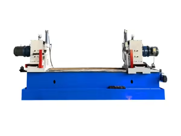
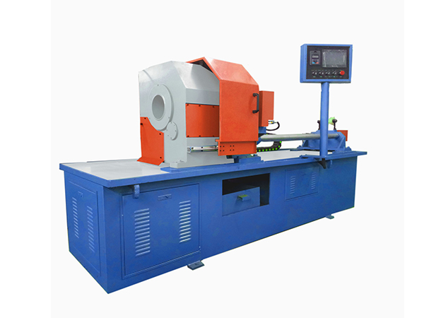
Spécialisé machines de traitement des rouleaux convoyeurs est conçu autour de ces étapes de production récurrentes car chaque opération peut influencer la relation dimensionnelle du rouleau fini.
La coupe des tubes doit fournir une longueur constante afin que le traitement ultérieur commence par une pièce prévisible La préparation finale doit maintenir une géométrie appropriée pour les composants liés au roulement L'usinage de l'arbre doit positionner les méplats, les rainures ou d'autres caractéristiques avec précision, tandis que l'assemblage du roulement doit maintenir l'alignement prévu entre la coque et l'arbre.
Lorsque le soudage fait partie de la construction, l'apport de chaleur doit également être contrôlé, car la distorsion introduite tardivement dans la production peut modifier la géométrie établie avec précision lors des opérations antérieures.
Le rouleau final reflète donc la qualité de l'ensemble du processus de fabrication L'inspection peut identifier la variation, mais elle ne peut compenser une séquence de production instable.
Pour la production industrielle, la répétabilité est particulièrement importante Un rouleau précis montre que la conception peut être fabriquée Un lot de rouleaux avec des dimensions, un écoulement et un comportement de rotation similaires fournit une preuve plus solide que le processus de production lui-même est contrôlé.
La sélection du matériau et de la surface doit correspondre à l
Le corps du rouleau peut être fabriqué à partir de différents matériaux en fonction de la charge, de l'environnement, des exigences de poids et du type de contact avec la courroie ou le produit transporté.
Les rouleaux métalliques sont couramment utilisés là où la rigidité structurelle et la durabilité industrielle sont importantes D'autres matériaux peuvent être envisagés là où un poids inférieur, un comportement à la corrosion ou des caractéristiques de contact différentes sont requis.
Le choix correct dépend de l’application plutôt que de la qualité universelle d’un matériau.
L'état de surface est également important Un rouleau exposé à l'humidité ou à des conditions environnementales agressives peut nécessiter une protection supplémentaire, tandis qu'un rouleau entrant directement en contact avec des produits sensibles peut nécessiter une surface différente de celle supportant le dessous d'une courroie.
Les traitements de surface et les revêtements devraient donc résoudre une exigence de fonctionnement spécifique L'ajout d'une protection plus importante ou d'une surface plus compliquée n'améliore pas automatiquement les performances du rouleau si l'application réelle ne le nécessite pas.
Les modèles d'usure peuvent également fournir des informations utiles pendant la maintenance. Une usure inégale de la surface peut indiquer un désalignement, une charge concentrée, une accumulation de matériaux ou un contact anormal avec la courroie plutôt qu'une simple mauvaise qualité du matériau.
Un rouleau de remplacement doit être spécifié à partir de l'installation vers l'extérieur
Les rouleaux de remplacement sont souvent commandés en mesurant l'ancien composant après qu'il a été retiré du convoyeur Cela peut fonctionner, mais cela peut également créer des erreurs si le composant usé a changé de dimension ou si des caractéristiques d'installation importantes sont négligées.
Une approche plus forte commence par la position de montage.
La géométrie de l'extrémité de l'arbre, l'espacement des supports, la longueur de la face du rouleau, le diamètre de la coque et les emplacements des roulements doivent d'abord être confirmés par rapport à la structure du convoyeur. À partir de là, la construction interne peut être évaluée en fonction de la charge et des conditions de fonctionnement.
Une spécification de remplacement complète peut inclure :
| Zone de spécification | Informations à confirmer |
| Position du rouleau | Transport, retour, impact ou autre devoir |
| Diamètre de la coque | Géométrie requise du convoyeur |
| Longueur de travail | Largeur de la ceinture ou du support du produit |
| Diamètre d'arbre | Exigence structurelle et de montage |
| Conception d'extrémité d'arbre | Plats, fentes, rainures ou filetages |
| Disposition des roulements | Exigence de charge, de vitesse et de rotation |
| Scellage | Contamination environnementale |
| Surface | Exigence en matière de matériel et de protection |
| Exigence d'épuisement | Géométrie rotationnelle |
| Droit d'exploitation | Vitesse, charge et durée de travail |
Cette approche améliore l'interchangeabilité car le nouveau rouleau est conçu autour de l'interface du convoyeur plutôt que uniquement autour de l'apparence du composant retiré.
Les problèmes de rouleaux répétés doivent être traités comme des informations diagnostiques
Lorsqu'un rouleau tombe en panne de manière répétée dans la même position de convoyeur, son remplacement par un autre composant identique peut rétablir temporairement le fonctionnement sans résoudre la cause sous-jacente.
La localisation de la défaillance peut révéler des informations utiles.
Si des problèmes de roulement se produisent à plusieurs reprises dans une zone, une contamination ou un désalignement du cadre peut y contribuer Si l'usure de la coque apparaît principalement sur un côté, la courroie peut ne pas entrer en contact uniforme avec le rouleau Si un rouleau de remplacement développe rapidement une résistance anormale, l'arbre peut être forcé dans une position de montage incorrecte par les supports environnants.
L'accumulation de matériau peut également modifier le comportement du rouleau Le matériau accumulé autour d'une section de retour peut augmenter la pression de contact ou interférer avec la rotation, tandis qu'un rouleau voisin endommagé peut modifier le support de la courroie et transférer une charge supplémentaire dans les composants à proximité.
Les équipes de maintenance devraient donc comparer la position problématique avec d'autres sections du convoyeur Si la même construction de rouleaux fonctionne normalement ailleurs, la condition de fonctionnement locale mérite une inspection plus approfondie.
Ce type d'analyse des causes profondes permet de distinguer un véritable problème de conception de rouleau d'une condition du système qui endommage de manière répétée des composants autrement appropriés.
Qu'est-ce qui définit un rouleau fiable pour les applications de convoyeurs ?
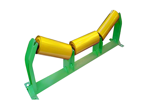
Un rouleau fiable n'est pas défini par un composant surdimensionné ou une spécification impressionnante Ses performances proviennent de la relation entre l'ensemble des pièces qui transportent et transfèrent la charge.
La coque doit maintenir sa géométrie sous la charge prévue L'arbre doit rester suffisamment stable entre ses points de montage Les roulements doivent supporter une rotation douce, tandis que les joints doivent protéger ces roulements de l'environnement de fonctionnement La fabrication doit maintenir les positions de la coque, de l'arbre et du roulement alignées, et le cadre du convoyeur doit installer le rouleau fini dans la géométrie pour laquelle il a été conçu.
Ces exigences doivent également correspondre au service réel du convoyeur Un rouleau utilisé en continu sous une charge importante nécessite un équilibre technique différent d'un autre fonctionnant seulement occasionnellement Une section de retour contaminée crée des exigences d'étanchéité différentes à partir d'une position de transport relativement propre.
La spécification la plus fiable commence donc par les conditions réelles de fonctionnement et s’oriente vers la conception des composants.
Cette approche réduit le risque de sélectionner un rouleau qui semble adapté en fonction de sa taille mais qui ne correspond pas aux exigences mécaniques de sa position d'installation.
Conclusion
La sélection d'un rouleau pour l'équipement de convoyeur nécessite plus que l'identification du diamètre, de la longueur et du matériau Le rouleau fonctionne comme une partie d'un système mécanique continu dans lequel la charge de la bande, l'espacement, le support de l'arbre, les roulements, l'étanchéité, la précision de fabrication et l'alignement du cadre influencent tous le résultat final.
La coque et l'arbre doivent être conçus ensemble car tous deux contribuent au comportement structurel sous charge Les roulements et les joints déterminent la façon dont le rouleau continue de tourner dans l'environnement de fonctionnement réel, tandis que le voile et la résistance à la rotation fournissent des indicateurs utiles de la qualité de fabrication et d'assemblage Ces caractéristiques deviennent particulièrement importantes dans les systèmes de convoyeurs longs où de petites variations sont répétées sur de nombreuses positions de rouleaux.
L'environnement d'installation doit également rester partie intégrante de la spécification L'espacement des rouleaux, la géométrie du convoyeur, les modèles de chargement, la contamination, la vitesse de fonctionnement et les conditions de montage peuvent modifier les exigences imposées à la même conception de base des rouleaux Lorsque des défaillances se produisent de manière répétée à un endroit, ces conditions environnantes doivent être étudiées avant que le rouleau lui-même ne soit supposé être le seul problème.
Un rouleau fiable pour l'utilisation du convoyeur est donc un ensemble équilibré plutôt qu'un simple composant cylindrique Lorsque la coque, l'arbre, les roulements, les joints, le processus de fabrication et la géométrie de l'installation sont tous adaptés au service réel du convoyeur, le rouleau peut fournir un support plus cohérent et un fonctionnement à long terme plus prévisible.
FAQ
À quoi sert un rouleau pour équipement de convoyage ?
Un rouleau pour équipement de convoyeur supporte une bande ou un produit transporté tout en permettant un mouvement contrôlé à travers le système de transport Selon sa position, il peut fonctionner comme un rouleau de transport, de retour, d'impact, ou de support direct, de sorte que ses dimensions et sa construction interne devraient correspondre au service d'exploitation réel.
Comment sélectionner le bon rouleau pour les applications de convoyeurs ?
Commencez par le type de convoyeur, la position du rouleau, la largeur de la bande ou du produit, la charge, l'espacement, la vitesse, l'agencement de montage et les conditions environnementales. Déterminez ensuite le diamètre de coque, l'épaisseur de paroi, la géométrie de l'arbre, les roulements, les joints, le matériau de surface et les exigences de qualité.
Pourquoi la conception de l'arbre est-elle importante dans un rouleau convoyeur
L'arbre transfère la charge du rouleau dans le cadre du convoyeur et détermine comment le composant est monté. Le diamètre de l'arbre, l'espacement des roulements, les méplats, les rainures, les fentes ou les sections filetées peuvent tous affecter le comportement structurel et la compatibilité de l'installation, rendant la géométrie de l'arbre essentielle pour les rouleaux neufs et de remplacement.
Qu'est-ce qui fait qu'un rouleau convoyeur développe un écoulement excessif
Un écoulement excessif peut résulter de la rectitude du tube, de la rondeur de la coque, de la position du siège du roulement, de l'usinage de l'arbre, d'un désalignement de l'assemblage ou d'une distorsion du soudage. Étant donné que plusieurs étapes de fabrication contribuent à la géométrie finie, un écoulement stable dépend du processus de production complet plutôt que d'une seule opération.
Pourquoi le même rouleau transporteur tombe-t-il en panne à plusieurs reprises dans une seule position
Une défaillance répétée peut indiquer un problème de convoyeur local tel qu'un désalignement du châssis, une contamination, une accumulation de matériaux, un chargement anormal, un montage incorrect ou un dommage aux composants voisins. Si des rouleaux identiques fonctionnent normalement ailleurs, les conditions environnantes au poste de défaillance doivent être inspectées.
 French
  English
  Spanish